Contributed by Buck Schmitt, CFPS, Territory Manager – Eastern PA and Mid-Atlantic, Kraft Fluid Systems
When designing hydraulic systems for mobile machinery, there are a variety of requirements that range from basic setup functions to extremely precise maneuvers. Let’s examine the more precise and critical functions.
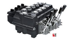
 There are several ways to approach hydraulic system challenges. Using best practices and understanding unique features from manufacturers, like Danfoss Power Solutions’ mobile proportional valves, will produce a machine that is safer and more productive.
A good example of a critical function on mobile machinery is the slewing function on an aerial fire truck, where the ladder is required to safely inch up to a window or fine tune the position of the water monitor. Another is the precise control of a conveyor motor that needs to deliver a specific amount of product by maintaining an exact speed. In these types of applications, the control valve can be the most important part of the system whether it is being controlled manually or electronically.
The first step in designing the best proportional valve into your system is to understand how fast the function is required to operate at full speed. This will determine the maximum required flow rate of the valve’s spool, but not how well the valve will need to meter flow. The critical aspect of how the function moves in its flow range will determine how the machine performs in the field. The Danfoss PVG 32 family of proportional directional valves offers two types of spools that affect the overall metering of flow to a function.
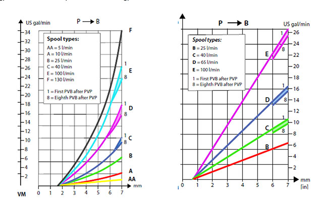
The progressive spool has a nonlinear parabolic curve in relation to spool travel and output flow. It provides fine control during the beginning of spool travel and is more aggressive toward the end of spool travel. A progressive spool gives an operator control of fine metering in the lower range of the spool and the ability to quickly accelerate to full speed for less precise movements where speed is preferred. This spool is the best choice for the aerial fire truck application noted above because it allows the operator the ability to finely control the swing of the ladder at very low speed so it can be slowly inched into a specific position. This spool also allows the operator to accelerate quickly and move the ladder over a large distance rapidly which may be valuable if working conditions quickly change.
The linear spool is a straight-line curve where the spool movement is in direct proportion to the flow within its range. So, for every millimeter of travel there is a predictable and proportional increase in flow. This is an excellent feature when completing a PID loop for speed or position. This type of spool is the best choice for the noted conveyor application because of its uniformity. Any adjustment of the spool will result in a predictable change of flow and will not be dependent on where it is positioned on the curve, like it would be on the progressive version.

If we compare the two spool types graphically, it will better illustrate their differences. The PVG spool length of stroke is 7 mm for both options. In the supplied graphs, the “E” curves illustrate spools with a maximum flow of 26.4 gpm (100 lpm). We see at 5 mm of stroke, the progressive spool flow will be 11 gpm and the linear spool would be 18 gpm.
Both spools are valuable in the right applications, however using the wrong one can limit or create challenges for both the operator and machine. It is always best practice to know the machine and understand the expectations of the operator.
Kraft Fluid Systems
kraftfluid.com


Why does (in the diagrams) the progressive spool seem to have twice the initial deadband (1.6 mm) compared to the linear spool deadband (0.7mm)?