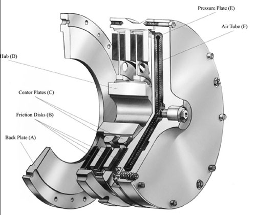
A clutch is a device used to transmit power from a driving member (motor/engine) to a subsequent one. As opposed to a mechanical clutch, a hydraulic clutch uses a fluid coupling device to transmit rotational power at variable operating speeds and without problems of shock loading. The fluid coupling device contains a driving turbine or torus also known as the pump, which creates flow within the chambers of the fluid coupling enclosure. This flow drives the output turbine, which is connected to the driven member of the transmission system.
When selecting a hydraulic clutch, important criteria to consider are what applications, performance specifications, and compatibility are desired.
Clutches have found applications in industrial, automotive, railway, airline, and agricultural settings.
The performance of a hydraulic clutch can be broadly specified according to its torque rating, power, rotational speed, and maximum pressure. The maximum torque is the greatest rated torque that the clutch drive can bear. The power refers to the operating power of the load that the clutch is intended to operate under. Rotary speed is the intended operating speed that the clutch has been designed to rotate at, while the maximum pressure is the greatest pressure that the clutch can withstand.
When considering compatibility of the clutch with driving and driven members, the clutch dimensions, clutch shaft geometry, and drive connection type are all important details. Significant clutch shaft dimensions are bore diameter, clutch diameter, length and weight. Clutch shaft geometry can be simply in-line, parallel, right angle, or another arrangement. The connection type of the clutch shaft can be in-line, through shaft, or flanged at the ends.
Hydraulic brakes
Hydraulic brakes are used to stop or slow moving systems. When triggered, they transfer pressure through the use of a fluid and this pressure triggers the braking mechanism. These braking mechanisms consist of brake types such as drum brakes, disk brakes, band brakes and cone brakes. Each of these braking styles have different braking properties, but they are all powered by the pressure from hydraulic fluid. The main specifications that come with brakes are speed, power, torque and maximum pressure.
When selecting a brake, the braking style is the first choice an engineer must decide upon. There are four main styles—drum, disk, band and cone. Drum brakes work by applying a braking pad to the rotating surface and slow the spinning surface down. Disk brakes work by squeezing the rotor of the rotating surface to slow it down. Band brakes work by tightening the material of the band around the rotating surface to slow it. A cone brakes works just like a band brake—however, the material is shaped in a cone as opposed to a band.
Combination packages
Because hydraulic brake and clutch components both use fluid power, they can be integrated and manufactured for ease of compatibility and installment into the application. When both clutch and brake components are present, braking can be facilitated by the disengagement of the clutch mechanism, which transmits the power needed to apply the brakes.


