Pressure valves are absolutely critical for the safe, reliable and precise control of hydraulic machinery. As anyone would assume by their name, pressure valves are any hydraulic component put in charge of controlling and/or limiting fluid pressure. Although it is possible for a hydraulic system to operate without a pressure valve, nearly every machine has at least one.
For the most part, pressure valves are just a spring pushing against a ball, poppet or spool, contained within some type of cavity or ported body. The spring pushes the ball, poppet or spool against a seat, at which point the valve is considered closed. When pressure in the circuit rises to a point sufficient enough to compress the spring, the valve starts to open and fluid is directed to tank at a rate equivalent to how far the valve is open.
Higher pressure will result in the valve opening further to bleed away fluid in an attempt to lower pressure.
Pressure valves are all very similar in their operation, and they differ only slightly in their application. The most common pressure valves are the relief valve, the pressure reducing valve, the counterbalance valve and the sequence valve, the latter being less common these days.
The relief valve is used to limit system or sub-circuit pressure by opening up to dump fluid to tank. Any part of the hydraulic circuit running in parallel to a relief valve will be subject to its control and reduction of pressure, as long as it remains the path of least resistance.
The counterbalance valve is a pressure valve typically plumbed on a hydraulic cylinder, and is designed to control motion for reliable and safe operation. Whereas a relief valve has two ports—one for the pressure port and another to the tank—a counterbalance valve usually has three ports, two being the same as the relief. The third port is a pilot port, where fluid is channeled from the opposing work port to pilot open the counterbalance valve. It essentially holds the cylinder load until the opposite work port tells it to open, allowing for safe and controlled movement of the cylinder, and preventing runaway loads.
The sequence valve is “normally closed,” just as the relief and counterbalance valves. The sequence valve serves the function of a self-piloted directional valve, in that it remains closed until pressure reaches the value of its spring setting. Sequence valves are used to create—you guessed it—sequential operation of circuit functions. For example, if a clamp operation is achieved at 2,000 psi, and then the drilling operation requires 3,000 psi, then you might set your sequence valve to 2,500 psi. When the clamp cylinder dead-ends and pressure rises past 2,500 psi, the sequence valve opens, allowing flow to reach the drilling motor.

Of the major pressure control valves used, the pressure-reducing valve is unique because it is the only one that is normally open. To prevent confusion to any electricians or electrical engineers reading this, normally open in hydraulics means normally flowing. So in the reducing valve’s neutral state, fluid passes freely through it. All other pressure valves are normally closed, which means they are non-flowing in their neutral state.
The pressure-reducing valve is also different from most other pressure control valves because it senses pressure downstream of itself. In contrast to that, a relief valve for example, senses pressure upstream of itself. For example, if you tee off a relief valve directly after the pump, then any conduit openly connected to that port will be subject to the control of that relief valve.
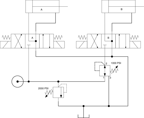
A pressure-reducing valve installed after a relief valve only monitors and controls pressure after itself. In the example circuit, the relief valve is set to 2,000 psi and the pressure-reducing valve is set to 1,000 psi. However, only port 2 of the reducing valve senses pressure, in this case for a maximum of 1,000 psi.
If the directional control valve A is operated alone, cylinder A has 2,000 psi available to it based on it being plumbed in parallel with the relief valve. Should load pressure rise above 2,000 psi, or should the cylinder reach the end of stroke, fluid will dump over the relief valve.
If directional control valve B is operated alone, and the same load forces affect cylinder B during extension, pressure at port 2 of the reducing valve will rise and start to close off port 1, as you can see by the direction the pilot lines are pushing. This prevents additional fluid from exiting port 2 towards the cylinder. As downstream pressure decays, pressure at port 2 drops below 1,000 psi and the valve once again opens to allow pump flow to cycle through the cylinder. The effect is not digital, such as can be seen with a pilot-operated check valve, for example, but rather the flow is smoothly metered down to reduce the hydraulic energy entering cylinder B.
Some pressure reducing valves are also pressure-relieving valves. A “reducing/relieving” valve has a third port that is connected to tank. Not only does it provide a drain for the spring chamber, ensuring that reducing pressure is unaffected by residual pressure from leakage, it gives excess pressure somewhere to go even if port 1 is blocked. Imagine in the previous example that pressure rises to 2,000 psi at port 1, and the reducing valve closes entirely. Although no further hydraulic energy is entering the B-side sub-circuit, load induced pressure could still remain at or above 1000 psi past port 2.
The relieving function would now bleed any pressure above 1,000 psi from port 3 back to tank, ensuring pressure cannot increase past 1,000 psi. If you went a step further, and mounted the reducing valve between the DCV and the cylinder, the reducing valve could then control pressure even if the machine was turned off. Any load or thermally induced pressure increase above 1,000 psi would simply be bled back to tank.
One advantage of pressure reducing valves is that they can be plumbed in parallel and provide as many pressure settings as there are actuators in the system. Reducing valves can be used to control force, such as may be required by a clamping function where the work piece is easily damaged. They can also be used to improve reliability to a sub-circuit of the machine. An example of this may be on a hydraulic press that requires full press tonnage of 5,000 psi from the piston pump, but auxiliary functions can manage with 2,000 psi. A pressure-reducing valve in the auxiliary sub-circuit reduces the pressure so that lower quality filtration can be used. This means that seals last longer and less heat energy is wasted through pressure drop.
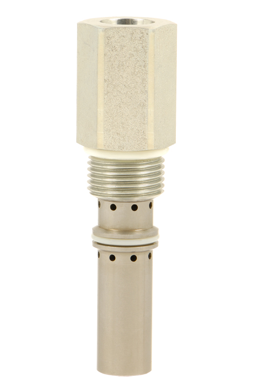
The most common reducing valve designs include cartridge valves, inline bodies and sandwich valves. Just like all hydraulic components, pressure-reducing valves can range from poor to high quality. Their rate of leakage, hysteresis, accuracy and reliability are all factors when selecting the correct one for your application, so spend time considering what your requirements are.

