By Josh Cosford, Contributing Editor
Flow dividers provide a unique solution to a specific problem in hydraulic applications — splitting flow while limiting its tendency to take the path of least resistance. Without a flow divider, any time you wish to split flow to two or more downstream subcircuits, the path with the lowest pressure will steal most (if not all) of the flow. Common designs include spool or gear type flow dividers that input a single flow path and output two or more at a given ratio. Other designs include radial piston and volumetric types.
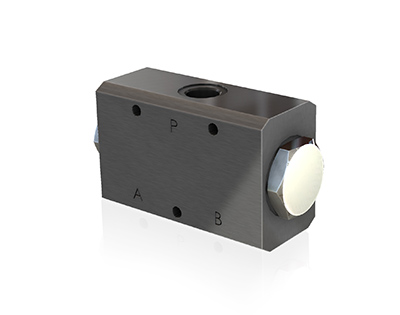
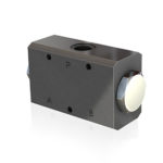
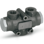
Spool-type flow dividers use a Y-shaped ported body and a clever method of pushing the spool toward the outlet port with the lowest pressure. This form of pressure compensation will choke the flow on the side, attempting to take the path of least resistance, thereby equalizing the pressure drop through each of the outlet ports. However, the method is not entirely accurate, allowing up to 15% or more of the flow to take the low-pressure path.
Spool flow dividers are particular in their operation, requiring they are specified for their ideal pressure and flow range. Should you operate with flow less than their specified minimum, they become unstable and imprecise. Conversely, with too much flow or too much differential pressure, the flow divider may lock up one flow path only.
Because flow dividers do not offer absolute accuracy, you can expect hydraulic cylinders to drift out of synchronization, primarily when they’re not provided with the opportunity to reach the end of stroke. Spool flow dividers may use a pressure compensated orifice to divert flow from a stalled cylinder to the active one, allowing for synchronization. Should your flow divider come with no inherent synchronization capability, cross port relief valves installed on the two work ports offers the same effect.
Flow dividers aren’t limited to 50:50 flow division, and with spool-type, you may find ratios such as 60:40 or 33:66. Custom ratios would be available for high volume OEMs, but the most common ratio is still 50:50. Motors benefit from unequal flow split, allowing two motors of the same displacement to rotate at the different RPM, or perhaps two motors of different displacement to rotate at the same speed.
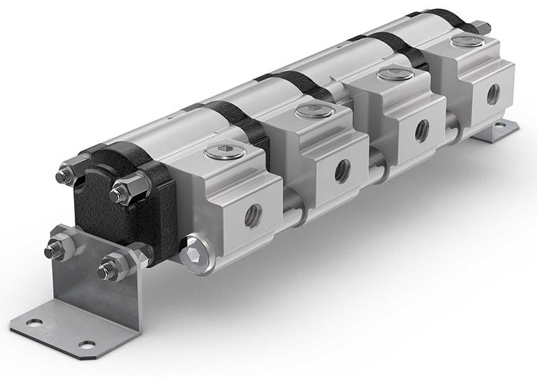
Gear type flow dividers are essentially hydraulic pump/motors connected by a common shaft. That single shaft ensures each gear section rotates at the same speed, thereby each flowing equally. Gear-type flow dividers tend to be more efficient than spool-type flow dividers. Less fluid is lost from one outlet port to the other, whereas with spool-type flow dividers, the clearances are larger to allow for lubrication of the spool.
Gear type flow dividers come with up to eight sections or sometimes more, which is an advantage over spool-type, which primarily offer just two outlet ports. However, for gear-type flow dividers to synchronize, you must install relief valves at each outlet port to send the fluid back to the flow divider inlet from a stalled actuator.
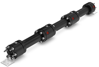
Most flow dividers are also combiners, meaning they will accept flow in retraction and extension, for example. In combining mode, synchronization still occurs and helps to keep multiple actuators in synch for both directions at the end of stroke. Gear flow dividers are inherently combiners, but spool-type dividers must be specified as such.
Two additional styles, radial piston type and volumetric dividers, offer high synchronization. Radial piston types divide a single flow into two output flows offer high volumetric efficiency and low speed capability. Volumetric dividers work only by volume dosage and the exchange between volume synchronizer and working cylinders. These are best suited for high-precision applications that require low pressure drop.

