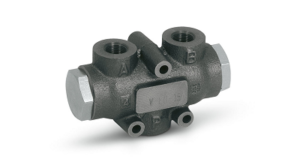
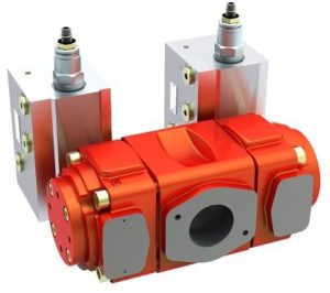
A flow divider is a hydraulic device that, as the name implies, separates flow into two or more parts. This lets a single pump simultaneously power more than one circuit. Two types of proportional flow dividers are the spool version; and the gear or rotary design.

Spool dividers split the input flow proportionally into two output flows. Common output ratios are 50/50, 60/40 and 66.6/33.3, but any ratio is theoretically possible.
The major components in a spool divider are a housing with an inlet port and two outlet ports; and an internal moveable spool. The spool features cross-drilled holes through the mid-point section, bisected by a center flow passage that runs the length of the spool.
The spool is free to move back and forth in the housing. Flow from the inlet enters through the passage in the center of the spool, divides and travels to each end of the spool. Flow exits both ends, passes through narrow gaps between the spool OD and housing, and out the ports.
If pressure on one side increases, the spool reacts to the pressure differential and shifts toward the other port. One outlet opens slightly more than the other but flow to both remains constant. Thus, both output flows are pressure compensated, and the flow division remains constant despite varying loads and pressures in the circuits. If input flow varies, the output flows will vary proportionally. And if one side is blocked, the other side will be blocked as well.
The gear-type divider can separate flow into two or more paths. A gear divider consists of a housing, two or more internal sections of mating gears, and barriers that separate the sections from one another. A common shaft connects the gear sections. Flow enters one end of the housing and routes through a channel to each of the gear sections. Fluid forces act on the gear teeth, causing them to rotate in opposite directions. Fluid between the gear teeth and housing is carried around to the opposite side of the gear section. As the teeth mesh, fluid is pushed out of each outlet port.
Because all the gear sections are connected, all the gears rotate at the same speed. The positive displacements of the gear sections produce a constant division of the flow. Inlet flow is divided proportionally between each section. Even if pressures in the output circuits vary, the output flows are proportional to the input. Should the input flow vary, output flows will likewise vary proportionally. And if one output is blocked, the others are also blocked. A relief valve prevents pressure intensification.

Gear-type dividers can also be used to combine return flow in circuits. Most spool dividers are not designed to permit reverse flow.
Rotary-gear dividers have a low pressure drop across the section and many offer efficiencies approaching 98%. Spool type dividers tend to require a sizeable pressure drop just to operate. That will generate heat, and engineers need to consider the inherent inefficiency when sizing them for an application. Gear-type flow dividers are also more tolerant of contamination. Spool-type dividers, on the other hand, have little internal leakage and can be highly accurate, although they tend to cost more than comparable rotary-gear dividers.
Many fluid-power component manufacturers make flow dividers for different flows, pressures, and with different accuracy levels and tolerance limits to suit many applications. Two common applications for flow dividers are multi-cylinder and multiple hydraulic motor circuits.
For cylinder applications, given the divider’s accuracy limits, inherent design characteristics could cause the path with the highest load pressure to receive a higher percentage of the flow. If a rigid mechanism ties the cylinders together, the lead cylinder can pull the lagging cylinder and cause cavitation.
Synchronization at the end of the cylinder stroke is a must, or engineers must compensate for any accuracy error that is expected with each stroke. In applications where the mechanisms between the two cylinders are too rigid, operating inaccuracy will cause the eventual lock-up of the system, with potential damage to the mechanical structure.
Hydraulic-motor drive systems will be affected in much the same manner. Rigid frames or mechanisms tying the motors together, such as vehicle wheels or conveyor sprockets, could potentially contribute to cavitation, lock-up, and pressure intensification. Variations in speed and/or possible lock-up can also be caused by differences in motor displacement, motor leakage, differences in wheel diameter, plus variations in the coefficient of friction between the wheels.
When using flow dividers, engineers should be aware of several application considerations. Like other hydraulic components, problems like entrapped air or excessive contamination can hurt performance. And operating at flows below the recommended limits can affect accuracy. In all versions there is no dividing or combining when flows are below the minimum rated input flow. For example, if flow in a spool divider starts at zero, the housing will essentially act as a tee until the unit reaches its minimum flow rating.
Likewise, inaccuracies are cumulative. Even if two or more devices in series individually operate within stated accuracy limits, the stack-up of acceptable errors may hurt overall system performance.

