By Josh Cosford, Contributing Editor
Nearly every single hydraulic system shares one thing in common — they’re run by a hydraulic power unit. Although some units are multitaskers, like the engine on a tractor, most often they’re purpose-built for the single task of converting mechanical energy into hydraulic energy. The scope of a power unit ranges from fractional horsepower electric units to monstrous constructions in the hundreds of horsepower.
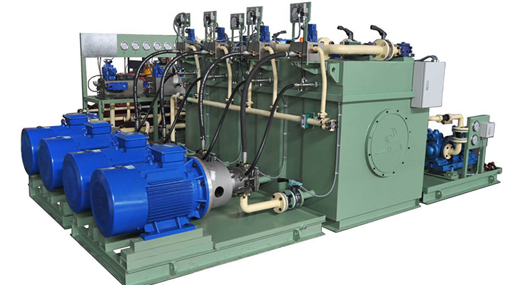
The power unit exists to supply the machine with hydraulic energy in the form of pressure and flow, without which you have idle components. You must first calculate the pressure and flow required by the actuators in the systems (see sidebar on Pressure and flow requirements). You may calculate this step more than once as you balance performance with economy, as very few machinery OEMs have no limits, financial or otherwise.
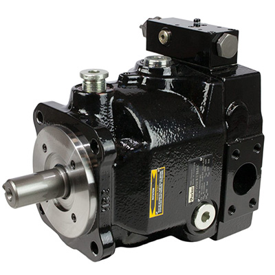
After you arrive at your pressure and flow requirements, you specify the pump type and size. Pump cost and complexity are vast but this dictates the level of performance you can expect to achieve with your actuators (see sidebar on Choosing a hydraulic pump). The type of pump used correlates with the direction you must take with reservoir design, filtration and complexity of pumping. A gear pump, for example, requires only suction and pressure lines. A load sensing piston pump, conversely, will add to that a case drain line and one or more hookups for the load sense network.
The pump now defined, the rest of the power unit can be built around it. You must now choose the size of your reservoir. Although opinions vary, you can’t go wrong with the advice to size it as large as possible. Limitations will exist for cost and footprint, but on average, expect to need at least three times pump flow at minimum, to ideally five times if it can be achieved. Every multiple of pump flow provides a precious extra minute of fluid dwell time. Reservoir size is critical for many reasons.
A large volume of hydraulic fluid relative to pump size gives time for fluid to cool before being drawn back into the circuit where heat soaks in once again. Large tank volume means large tank surface area, and in addition to the first point, this large surface provides a radiation layer to improve cooling. Additionally, with more fluid, particles settle more effectively than if they immediately re-enter the circuit, as with smaller tanks. Opposite to the settling of particles, air bubbles are given more time to rise, reducing the potential for cavitation-related damage from aeration.
After you calculate tank volume, you must now consider the reservoir construction type. Reservoir style (see this post on Which tank style to choose) plays an important role in ensuring the pump inlet conditions are ideal, preventing conditions favorable to cavitation. Economics are also primary here, ranging from the vertical type at the low end, to the L-shaped at the upper end. The former is compact but difficult to service, while the latter is highly serviceable but large and expensive.
Highly complex hydraulic systems consist of many components—some related to the function of the circuits, like manifolds, directional valves and pressure valves—and other components required for fluid conditioning and monitoring. Filters, heat exchangers and pressure gauges are components added to ensure safe and reliable power unit operation. Because of ease and convenience, as many components as possible should mount to the reservoir. As such, these components command much real estate, and reservoirs are oversized to accommodate.
 Use your hydraulic schematic as the first step in the power unit creation process. A hand drawn schematic helps you choose actuators and major components, but a detailed drawing helps with the visualization of component layout. A circuit drawing should be modified to include every component that will exist on the power unit, not only for the assembly technician to understand how to install and plumb all the components, but for future troubleshooting and repair.
Experienced hydraulic designers know what a power unit needs, but seeing the circuit helps spot gaps where less obvious components should be drawn, and then subsequently added to the bill of materials. Test points, ball valves, bellhousings, drive couplers etc., are all important and should be included. Once a schematic is complete, a bill of materials (BOM) can be created from it.
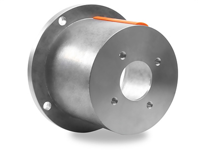
The most important set of components is the pump/motor assembly. It includes the chosen pump, a motor of adequate power capacity, a pump-motor mount and drive coupler set. The pump/motor mount — often called the bellhousing — rigidly fixes the C-Face electric motor to the pump and provides a gap to install the couplers. A coupler slides on the motor shaft, its mate slides on the pump shaft and then a synthetic rubber insert is placed between them before the couplers are pushed together and fixed in place with set screws. Be sure to select a coupler set rated for the required horsepower and pressure spike potential.
Once together, the pump/motor assembly is mounted to the reservoir, preferably with isolation mounts. These mounts are either welded or bolted to the reservoir and consist of two metal plates galvanized onto either side of a chunk of rubber. This isolator prevents excessive pump/motor vibration from resonating through the steel plates of the reservoir; an important requirement because hydraulic power units are already prone to nasty harmonic noise pollution.
In succession, the remaining “fixed” components are mounted to the reservoir. Accumulators mount off the side, valve banks to the top, filtration inside or on top, level/temperature indicator located to the side, ball valves (very important!) hard plumbed to the suction port, and any other component either welded or bolted to the tank are now installed.
With all fixed components now complete, you can fabricate the power unit’s plumbing. Most designers prefer tube but it is timelier to fabricate. It is semi-permanent and is more reliable in the long run. Hose can be used for plumbing as well, although hose invariably fails. Hose has its place, however, especially if noise and vibration is a concern. Tube transmits vibrations more readily, but hose can often dampen it. Most frequently, you plumb a power unit using a combination of hose and tube.
At the end of fabrication, the unpainted components are removed, and the power unit is cleaned and prepped for paint. Epoxy paint is best because it resists oil and provides a durable finish. When the paint dries, the technician re-assembles the unit, and the final stages of power unit fabrication begin.
The electrician now wires the electrical components, and this includes adding any electrical enclosures, transducers, switches etc. Wiring of the motor itself will often occur on-site at commissioning, but the electrician wires the valves and control boxes when the power unit is manufactured, to allow for testing. Once electrical is complete, the technician fills the tank with oil and jogs the motor from the electrical panel to ensure the motor is turning the correct direction. The technician turns on the pump, checks for leaks and tests the HPU at pressure. The final step, after successful testing, includes draining the tank, installing on a skid and wrapping up for shipping.



Just an editorial comment. “site” is a place and you might do the work “on-site”. “sight” is the ability to see and “on-sight” would be more correctly “upon-sight” and means when you see something.