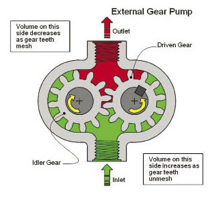
Gear pumps can be either internal or external styles. External gear pumps are one of the most popular types used in modern hydraulic systems. Gear pumps produce flow by using the teeth of two meshing gears to move the fluid. Their simple construction ensures limited purchase costs and servicing. Gear pumps work under heavy operating conditions and transmit high amounts of hydraulic power. They feature decent hydraulic, mechanical and volumetric efficiency, compact dimensions, and low weight/power ratio. This balance of efficiency and economy make external gear pumps a popular choice for auxiliary systems in a number of different machines.
External gear pumps can be equipped with straight spur (the most common type), helical, or herringbone gears. In operation, the drive gear and driven gear rotate, creating a partial vacuum at the pump inlet (where gear teeth unmesh) that draws fluid into gear teeth. Gear teeth mesh at the outlet, forcing fluid out of the pump.
Internal gear pumps contain one internal and one external gear. They pump fluid in the same manner as external spur gear pumps. In the basic design, the internal gear, which drives the outer gear, has one tooth less than the outer gear. As they mesh, the teeth create sliding seal points. Because their transition zone from low to high pressure (the area over the crescent) is relatively long, internal gear pumps can offer lower noise levels than some other types of pumps.
Gears are made of special steel and are often case hardened and quench hardened. Then gears are ground and fine finished. Proper tooth profile design and geometric proportions can reduce pulsation and noise levels during pump operation.
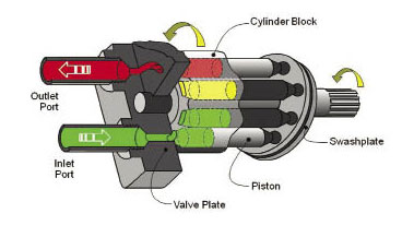
Piston pumps supply high flows at high rpm. Two types of piston pumps, axial- and radial-piston, are manufactured in both fixed- and variable-displacement versions. Axial-piston pumps contain one or more pistons that convert rotary shaft motion into axial reciprocating motion. An angled cam (or wobble plate) rotates, causing pistons to reciprocate and take fluid in as they move toward the thin part of the plate. Fluid is expelled as pistons approach the thick end. In one version, the bent-axis design, both pistons and shaft rotate, making a wobble plate unnecessary. Bent-axis pumps use the drive shaft to rotate pistons.
With the longer sealing paths along the piston walls, piston pump efficiencies tend to be higher than other types of pumps. In addition, variable-displacement pumps can provide savings by only providing the pumping necessary for the function, saving additional energy and costs.
Radial-piston pumps (fixed-displacement) are used especially for high pressure and relatively small flows. Pressures of up to 5000 psi are common. Variable-displacement is not possible, but sometimes the pump is designed in such a way that the plungers can be switched off one by one, so that a sort of variable-displacement pump is obtained.
Radial-piston pumps are characterized by a radial piston arrangement within a cylinder block. As pistons reciprocate, they convert rotary shaft motion into radial motion. One version has cylindrical pistons, while another uses ball-shaped pistons. Another classification refers to porting: check-valve radial-piston pumps use a rotating cam to reciprocate pistons; pintle-valve pumps have a rotating cylinder block, and piston heads contact an eccentric stationary reaction ring.
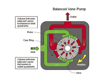
Rotary vane pumps (fixed and simple adjustable displacement) generally have higher efficiencies and lower noise levels than gear pumps. They can be used for mid pressures of 2500 psi and modern units can exceed 4500 psi in continuous operation.
Some types of vane pumps can change the center of the vane body, so that a simple adjustable pump is obtained. These adjustable vane pumps are in general constant pressure or constant power pumps: the displacement is increased until the required pressure or power is reached and subsequently the displacement or swept volume is decreased until equilibrium is reached.
A critical element in vane pump design is how the vanes are pushed into contact with the pump housing, and how the vane tips are machined at this very point. Several type of “lip” designs are used, and the main objective is to provide a tight seal between the inside of the housing and the vane, and at the same time to minimize wear and metal-to-metal contact. Forcing the vane out of the rotating center and towards the pump housing is accomplished using spring-loaded vanes, or more traditionally, vanes loaded hydrodynamically (via the pressurized system fluid).
- Pressure
- Angle
- Related torque
- Weight
- Mounting configuration


Thank you for explaining how hydraulic pumps work. I have been trying to get a better understanding of this because of a project that I am working on. Do you know what kind of material the exterior of a pump is typically made of? Thanks for the info!