While many utilities vehicles use fluid power for power and control, lift platforms and telehandlers especially rely on the reliability and safety of hydraulics.
By Josh Cosford, Contributing Editor

The utilities sector is any industry related to the delivery of essential infrastructure services to end use customers, and these services include water, sewage, electrical, natural gas and communications, to name a few. Each of these industries are provided as a public service, whether through local government or private enterprises serving consumers on behalf of the government. As a public service, these industries are highly regulated, especially as it pertains to the safety of consumers and workers alike.
Machinery used in utilities sectors must be productive and efficient, but also safe and reliable. Luckily for you and I, fluid power excels at these qualities, and hydraulics is the primary source of mechanical force transfer in utilities machinery. Hydraulics is not only powerful yet compact; it also reliable, controllable and extremely safe. Because so much can go wrong working with machinery on public roads, buildings and homes, safety of machinery is the top priority, regarding both operators and civilians.
The nearly-incompressible nature of hydraulic fluid makes it both highly controllable and highly safe. Strictly mechanical systems are more difficult to control, especially smoothly. Electrical actuation in mobile machinery is hardly a blip on the radar, so we won’t discuss that point. Because many utilities applications involve the movement and lifting of persons, extra care is taken to mitigate potential harm, which could occur in various forms.
Smooth, safe lifting
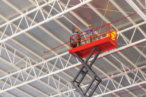
A scissor lift platform, for example, is manufactured to lift one or more persons to work height as required, such as for electrical or plumbing installations. These platforms can lift five-hundred pounds or more of humans, tools and supplies, and do so incredibly smoothly with an incredible safety and reliability record.
The ability of hydraulics to control the rate of fluid molecule motion is a key factor which makes hydraulics the top choice for man-lift applications. Fluid can be metered, stopped and instantly reversed through manual, hydraulic or electrical operators, permitting either full pump flow or literally drops of fluid. The motion-control component known as the counterbalance valve is a prime example of hydraulic metering providing safe, smooth control over the lifting platform regardless of incoming flow.

I have included a simplified sample circuit as could be used for a telescopic lift. The pump in this case would be powered by a dc motor and provide flow only when required, which would be when the operation powers the lift with its electric controls. The pump will turn on, bypassing the counterbalance (CB) valve and passing straight through the hold valve. Because the hold valve is a one-way poppet, when the valve is in its neutral state, it performs as a check valve, allowing the flow to the lift cylinder, raising the platform.
The magic in this circuit happens on the way down. The speed of a dc motor is easily varied by changing the incoming voltage, so the up and down velocity of the lift can be feathered smoothly to provide the users with confidence and ease as they position. However, when applications are capable of movement without pump power, such as with a loaded platform, care must be taken not to overrun the desired down speed. If our platform is loaded above its rated weight capacity, it may drop at an uncomfortable or unsafe speed above what is being asked of by the pump, regardless of whether it’s spinning more slowly.
The counterbalance valve, also known as a motion control valve, is a fantastic way to control or prevent overrunning loads. It works by sensing the pressure at the work cylinder’s opposite port, this time attached to the rod side, and using the pressure from that port to open the valve to allow descent. The inlet to the CB valve is plumbed to the cap side of the cylinder, and with a trick spool design, compares pressure at this port to the pilot port. The machined areas of each side of the spool have a specific, known differential making it easier for the valve to open using pilot pressure compared to direct pressure.
Let’s say our counterbalance valve in this example has a 3:1 pilot ratio, meaning it takes 2,800 psi of work pressure directly at the inlet of the valve to crack it open against spring pressure, but it will take just 933 psi on the rod side of the cylinder to allow flow to pass and the cylinder to lower. With a counterbalance valve, you absolutely need to see pressure coming from the pump to lower the cylinder.

What’s good about a counterbalance valve is the performance under various levels of flow. Within a reasonable range it will smoothly control descent even with variable flow rate from the pump. If the pump flow is reduced, the rate of pressure rise at the pilot port is reduced, and the subsequent rate of descent is smoothly matched. CB valves are not digital like pilot-operated check valves, which are either open or closed, and will chatter if they find themselves caught between. This is why the counterbalance valve is also called a motion control valve.
As a final point related to this sample circuit, you will have noticed the manual blocking valve teed off the cap port of the cylinder. It feeds downstream into a fixed orifice, in reality likely installed into the valve itself or a fitting at its port. Should there be a power failure and the pump is not able to provide pilot pressure to operate the counterbalance valve, this valve will provide a backup method of safe descent. The orifice will be sized as such to provide very slow movement, since flow through it is based entirely on load pressure.
Rising electronic controls
Modern mobile machinery is increasingly managed with sophisticated electronic controls, especially as the price of such components drop amid a heavily competitive mobile machinery market. In the past, hydraulics could be used to accomplish crafty features for improved safety with no electronic intervention.

The telehandler is great for lifting people and equipment into difficult, out-of-reach places not possible with telescopic lifts. However, because it is capable of lifting very high with long reach, it can be overloaded with potential to tip the entire machine, bringing down the boom and the persons at the top. The higher and farther a lift extends, it increases pressure on the boom cylinder. Traditional hydraulics will employ a pressure reducing valve in the cylinder circuit that prevents the machine from moving the work platform any higher or farther, preventing accidents.
Sophisticated electronics, including pressure transducers, accelerometers and multi-axis inclinometers can now sense exactly the load, velocity and angle of both the machine and work platform. The controller uses closed loop control to keep the passengers out of danger so that they always move smoothly, and should the vehicle or boom angle become too severe, prevent the load from becoming out of balance by restricting movement.
With utilities applications, safety isn’t just in the way fluid power systems are controlled, but rather it’s sometimes in how they’re made. A good example is the use of non-conductive hydraulic hoses for all utilities applications involving aerial lifts enabling persons to work on high-voltage wires. Non-conductive hoses graded R7 and R8 are have limits of permissible conductivity, even as voltage nears 75,000. The construction of the hose needs to be with not only non-conductive outer carcass material, but also the inner tube and reinforcements.

Should a traditional hydraulic hose with standard steel-braided construction accidentally make contact with a high-voltage wire, it could electrify the entire machine as it transmits through the hose and all the metal components attached upstream. Non-conductive hoses employ either textile or synthetic braided material for reinforcement, insulating the hydraulic hoses from the rest of the machine, reducing the chance of electrification.
As the world’s population continues to grow, the utilities sector must grow with it. More people means more essential services, and with the increased requirement on infrastructure comes increased use of hydraulic machinery to service those needs. Hydraulic motivation is already a favorite of mobile machine designers, and the case for fluid power in utilities applications to improve safety will remain pertinent.


