By Josh Cosford
Hip hip hooray! Hip hip … okay, I’m over it. Anyhoo, I wanted to write about the multiple methods to control multiple hydraulic functions, each with multiple benefits of their own. Two popular methods are common to either the industrial congregation or the mobile cartel, but I’d like to present a third, nearly insupposable approach using aluminum manifolds and cartridge valves.
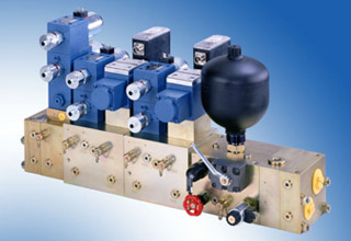
The first design is, by far, the most common method used in the industrial hydraulic market, with the extensive use of integrated manifolds on hydraulic presses being the exception, and that is stack or sandwich valves.
The modular stack valve goes by many names, such as CETOP 3, NG6, D03, size 6 etc.—to use the most common size as an example. Although confusing, all terms refer to the same diamond-ported valves mounted on subplates or bar stock manifolds. The size of industrial valves start at D03 and range through D05, D06, D07, D08 and D10, covering nearly any conceivable hydraulic flow range. At some point in ancient history, there was a D02 valve, but I’m not even old enough to have ever seen one, so we’ll pretend it doesn’t exist.
These are called modular valves for a reason, and their primary advantage is the easy creation of custom hydraulic circuits with off-the-shelf parts. Nearly every conceivable valve is available in the stackable variation, including directional valves, relief valves, flow controls, reducing valves, counterbalance valves; you name it. Go ahead, name it!
Each portion of the circuit can be controlled with one stack, using only the auxiliary valves needed to meet the requirements of the actuator being operated. The crusty bun of our sandwich valve stack is the valve plate or bar stock manifold on the bottom, and the directional valve (usually solenoid operated) on top. The stale and unappetizing meat slices of our sandwich are the auxiliary valves layered like cinder blocks as high as the stretch of the threaded rod holding it all together will allow.
It is important to remember the valves closest to the bottom are also the valves closest to the actuators, so if a P-Port flow control is generally installed near the top, and an A-Port counterbalance valve tends installed close to the bottom, making it that much closer to the work ports. This is more important to remember when two valves are in the same work line, like both a P-Port flow control and a P-Port reducing valve (I would put the flow control lower in the stack). Building a circuit with stack valves can be pricey, and with so many components bolted together with only crushed o-rings to prevent leaks, those leaks will be inevitable.
Josh Cosford, Certified Fluid Power Hydraulic Specialist, is with www.fluidpowerhouse.com.


