Every hydraulic system needs a pump. Whether your application is industrial manufacturing, mobile construction, truck, agricultural equipment, or marine work, it needs a pump to supply flow and meet application work requirements. Here’s how to pick the right one.
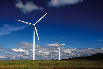
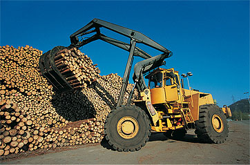
Hydraulic systems are used for tasks ranging from the very traditional to the very modern, such as wind turbines. Known for adjustable, controllable power transmission to a variety of actuators, they have one thing in common: the heart of the system is a hydraulic pump.
Basic pump designs are piston, gear and vane. Of those, gear and vane pumps are primarily used for fixed-flow applications. Today, the trend to variable-displacement pumps with higher pressures and improved efficiency has encouraged the growing use of axial variable-flow piston pumps. So what is the correct pump for your application?
Fifteen key questions
To start the selection process, answer these questions:
• What is the application? Is it limited duty or sophisticated equipment requiring high speed or high power density?
• What is the power or force required to fit the system you are building?
• What types of actuators are to be used?
• What are the speed and power requirements for each function or multiple simultaneous functions and total duty cycle?
• What are the system operational requirements? Specifically …
• How hard and how long are you going to run the system?
• What flow rates are needed? Fixed or variable flow?
• What environment will the equipment operate in?
• What will be the operational temperatures?
• What fluid will be used, and what viscosity?
• How fast does the pump have to work: cycle rate speed/response time?
• How fast will the pump be driven by the prime mover?
• What noise levels can be tolerated?
• Are you going to warranty the system and for how long?
• Will you provide aftermarket service for this system/equipment?
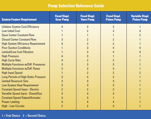
The answers will quickly point to the pump type and ratings needed. If, for example, your application is a limited-duty log splitter with pressures around 3,000 psi, your best pump option would probably be a fixed flow Hi-Low gear pump so system speed and power can be matched closely with the pump. But if your system requires continuous 24/7 operation with the pump running full tilt, better to select a pump that has long bearing life. The table – Pump Selection Reference Guide — rates each pump type on a scale of 1 (first choice) to 4 by system feature requirements.
Specific selection considerations
Open or closed circuit: Pumps operate in either open or closed-circuit applications. In a closed-circuit system, the flow is looped from a hydraulic pump outlet to a hydraulic motor and directly back to the inlet of the pump. Closed circuits are typically used for single rotary function applications such as powering a hydraulic winch motor or propelling a wheel motor. For applications requiring simultaneous multiple functions, such as propelling a vehicle and raising a bucket, or for cylinder applications, an open circuit is typically selected. In a closed circuit you are feeding the pump from the motor and could starve the pump if it were used with a cylinder function. Variable-displacement pumps can be used in both closed and open circuits.
Match power to load: A key advantage of variable-displacement pumps is that output (flow to the actuator) changes to match application requirements. If you want the hydraulic motor to operate at a specific speed, the pump will deliver the flow required. The pump can be controlled manually or electrically to provide needed displacement.
Variable-displacement pump control options: The three most popular mechanical control options are pressure compensators, flow compensators and torque (mobile applications) or horsepower (industrial applications) limiters. All send a hydraulic pressure signal to the pump, telling it what to do.
Pressure compensator control is the most basic. A valve is mounted on the pump body that directs oil to and from a stroking piston in the pump to determine the appropriate swash plate angle. (Swash plate angle controls displacement.) At full angle (maximum flow), the internal valve vents the stroking piston. When oil is ported to the stroking piston, it pushes the swash plate to a lower angle to reduce pump output flow and slow the hydraulic motor or cylinder. The pump displacement is maintained when the spool shifts over to direct oil into and out of the stroking piston. The swash plate then moves the displacement angle required to keep the pump at the pressure set in the circuit. Variable displacement pumps always provide the exact flow needed. You set the valve at maximum pressure, but the flow will be as needed to avoid heat generation and save energy.
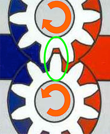
A gear pump carries fluid between the teeth of two meshing gears. One gear is driven by the drive shaft and turns an idler gear. Gear and vane pumps are primarily used for fixed flow applications; they are positive displacement pumps that deliver the same volume for each cycle of the pumping element.
Flow compensator control (sometimes called a load sensing control) can be both a load sensing and pressure compensating control. It senses the pressure needed to move a hydraulic motor or cylinder and sends a signal back to the pump control with the flow and pressure needed to do the job. This makes for a more efficient circuit, and is common in mobile equipment for more efficient use of power.
Torque limiting controls: (In industrial applications, this same control is referred to as a horsepower limiting control.) These controls limit the power the pump can draw. If you have a 100 hp diesel engine operating at constant speed, this control allows you to set the torque limiter (for example) at 50 hp. This leaves 50% of the available power to drive other functions. In operation, the pump varies displacement and maintains a constant output torque. Torque limiters are often used in applications where you want to get as much power as is available without stalling the electric motor or diesel engine.
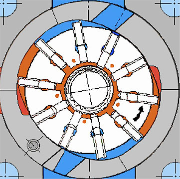
In vane pumps, vanes slide in slots in a rotor that rotates in an oval or eccentric housing. During rotation, atmospheric pressure forces oil into the inlet side of the pump. As the space or volume enclosed reduces, the liquid is forced out through the discharge port.
Electronic controls are used to signal a pump-mounted valve that controls the displacement for the flow or pressure level needed. These controls range from simple to sophisticated. While this technology is more expensive, ability to modify pump operation electronically allows for improved operation and efficiency.
Operating parameters
Operating pressure: All pumps are designed and rated to handle a specific maximum pressure before failure a
nd/or breakage. At minimum, select a pump that can handle the maximum pressure that will be run. Once your circuit is defined by the size of the actuator (hydraulic cylinder or motor) needed, that power level will define pump operating pressure.
Pump drive speed: To fill the pump at the inlet port, we depend on atmospheric pressure to push oil into the pump. The faster the pump is turned, the more oil can be drawn in. However, the faster the pump is turned, the harder it is to get oil into the pump based on any restrictions in line size, line length, and port size. So pumps are rated for a specific drive speed for given inlet conditions. Most variable displacement pumps are sized to operate at one atmosphere with minimums of at least 1,800 rpm for an electric motor or 2,400 rpm for a diesel engine.
Temperature: Typically, fluid viscosity and temperature are linked. The main concern with temperature is oil viscosity. High or low extremes in temperature or viscosity (or both) can reduce internal pump oil films and cause failure. In addition to using the oil to transmit power, the same oil is being used to lubricate the pump. Variable-displacement piston pumps have very close tolerances, allowing a film of oil to prevent the pump from experiencing abrasive damage.
The hotter the system, the lower the oil viscosity, and the less protection you have against metal-to-metal contact. Conversely, cold temperature and high viscosity can also limit the ability of the oil to flow and lubricate the parts.
Operating temperatures can also impact the type of pump sealing material to be used. Pump temperatures in excess of 105º C (220º F) will require Fluorocarbon or other type of suitable seals while pumps operating in the -40º C temperature range would use Nitrile or other suitable seals. Pumps are rated to run at specific viscosity while at high temperature.
Operational hours: Pump life is hard to define because many variables come into play – fluid type, contamination, viscosity plus pressure and how much the pump is stroked. The operational hours rating used by industry is mean-time bearing life. At full power, how many hours can you operate before “X” percentage of pump bearings will fail? For example, a B10 bearing life means that not more than 10% of the bearings would fail in the listed time. B50 means that up to 50% could fail.
Volume: Pumps are sized by how much output flow is required. Example: you want to move an actuator at a certain speed. Speed translates to the volume of oil you put into it. The key is to look at the desired end result of what you want the pump to do, such as …
• How many stages do you have to run?
• What is the size of the cylinder or motor?
The required flow can then be calculated in gpm or lpm. Calculation will define pump speed needed to provide the required flow.
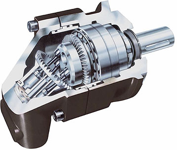
Piston pump designs include axial inline, bent axis and radial. Bent-axis pumps are generally used for fixed-flow, high-pressure applications. Radial designs are not in common use today.
Another factor is pump efficiency as some pumps are more volumetrically efficient than others due to the internal leakage used to lubricate the pump. Example: if you put 100 gallons in, you might lose 3 gallons due to internal leakage. That leaves 97 useful gallons (the pump is 97% volumetrically efficient).
A different pump may only be 90% efficient. A concern when sizing a pump is its efficiency to ensure there is sufficient output flow.
How much power is needed to turn the pump at the flow and pressure required for the job? In addition to volumetric losses in the system there are also mechanical losses. Volumetric and mechanical efficiency combined make up the overall efficiency of the system when determining the power needed to drive the pump.
Fluid type and viscosity: Typically, pumps operate on mineral-based oils with a viscosity rating to match the operating temperature. The preferred viscosity range for piston pumps to get the best lubrication lifespan is 30 to 50 cSt at 100F. Note that in selecting viscosity range, you must also be concerned with the other system components.
Fluid compatibility can also be an issue. The phosphate-ester fluids used in commercial aircraft require the use of Ethylene Propylene seals. Also, there are pump seal selection issues with water-based and biodegradable fluids. These special fluids can also alter the pump ratings. For a water-based fluid, the pump might be de-rated from 1800 to 1200 rpm, and the pump’s operating pressure could also be de-rated.
Inlet conditions: As noted, atmospheric pressure forces oil into the pump. If the pump reservoir is located below the pump inlet, it could pose a negative vacuum condition. Location of the reservoir is critical, as are factors like size of inlet hose and number of fittings or right angle inlet turns in the inlet from reservoir tank to pump. A piston pump can typically handle five inches of mercury vacuum at the pump inlet. There is also a limit as to how fast the pump can run if you have a bad inlet condition. The standard recommended velocity of 1-1.5 meters per second (3-5 ft/second) value has been determined experimentally to provide adequate inlet flow without excessive pressure drop. It also ensures that the fluid is fairly laminar as it flows into the pump. Turbulent flow will cause the oil to separate into air bubbles, which can cause damage and noise.
Case drain pressure: Remember, internal oil leakage is the oil used to lubricate the pump. Hence, it is important to allow the oil to vent to prevent a significant oil buildup in the pump’s case. Typically there is a drain on the pump to take the oil back to the reservoir. This drain limits the pressure of the oil in the pump case, and ensures the slippers on the end of the piston and other components are protected.
Case drain pressure can also be affected by length of the drain line back to the reservoir, or by the drain line size. If too small, not as much oil will get through to the reservoir and backpressure will build. With most piston pumps the goal is to keep case drain pressure at 10 to 15 psi.
Gear and vane pumps typically do not have separate case drains. Any oil that leaks out from the pressure side is redirected to the inlet to be pumped again. As a pump wears, this leakage increases until the output of the pump is reduced to cause noticeable loss of speed in the actuators. Piston pumps typically have a separate case drain ported external to the pump.
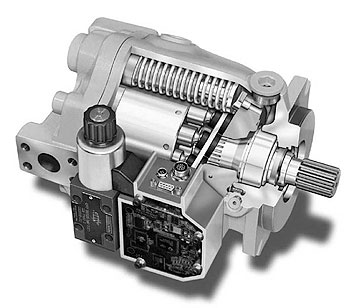
Axial variable-flow piston pumps are recommended for handling flow or pressure changes in a hydraulic system. These pumps offer higher efficiencies in power use. Fluid is pumped as the cylinder block rotates and the pistons bear against a cam. In variable displacement units, the cam is movable and commonly referred to as the swash plate.
Performance measurement: You are concerned with output flow, output pressure, power and the speed of the pump. Pump-makers’ literature includes charts of output flow at different pressures and speeds that will assist you in obtaining necessary flow. For pressure, the literature will state the maximum high-pressure range you can operate the pump on a continuous basis. For speed, if you have an engine that will operate at 2,400 rpm, and the pump will be mounted directly to it, then the pump will operate at 2,400 rpm. The charts will then help you select a pump that can deliver the flow you require. Also, there are charts that show how fast the pump can operate and provide full flow. If you don’t need as much flow, the charts also show how fast the pump can run at a pa
rtial flow. Pump efficiency ratings are also provided. Typically, the chart information is based on actual performance test data. Even so, it’s wise to make certain the data provided are actual.
Noise reduction: Noise issues will be addressed in Part II of this article, to be published in a future issue of Design World.
Parker Hannifin
Hydraulic Pump Div.
www.phpump.com
::Design World::

