
By Justin Wheeler, CFPHS, C-Series/Bent Axis Project Manager, Hydraulic Pump Div., Parker Hannifin
The ideal in hydraulic system design is to match overall efficiencies to the application performance expectation. This requires the designer to first match the motor, then the pump to a specific system performance expectation. Whether the requirement is to do something within a specific time frame, or in handling a given amount of load, the design of the entire system will change depending on the motor selected.
A hydraulic motor is a hydraulic actuator that, when properly connected into a hydraulic system, will produce a rotary actuation. This can be unidirectional or bidirectional depending on the system design. Motors are similar in design to pumps only where a pump takes a rotary actuation to move hydraulic fluid out of the unit, whereas a motor will take flow into itself and put out a rotary actuation.
The motor selection comes first in the process because application design best practices require that you start with the load requirement, then work back to the prime mover—the pump that will put the fluid power into the motor selected to deliver the performance goal.
Each motor type—gear, vane, in-line piston, bent-axis piston and radial piston—has a specific performance profile. So, knowing the application performance requirement and which motor type best meets the objective is the first step. Then it’s necessary to evaluate the cost of your motor options along with the degree of complexity you want for the overall system.
In the end, it all goes back to the application’s performance expectations. Some have severe duty cycles, while others do not. If, for example, you consider running a low-efficiency, lighter-duty motor into a higher-duty cycle application, the life of the motor will be less than the life of a higher-duty cycle motor that is designed to operate in those types of environments. It is important to understand what operating pressures and flows are required for the motor selected to achieve the application performance expectations.
Each motor type has its own set of applications where they are a better choice than others. For example, if a small gear motor designed to operate at a max of 3,000 psi and 1,000 rpm is put into an application that requires it to run consistently at 3,000 psi and 1,000 rpm, the motor will be running in a “corner” overstressed condition and have a reduced life—even though it is technically within its ratings. The better motor choice would be a motor with higher ratings that will live longer in the application. Granted, there is a greater cost in going with a higher rated motor. The final decision always will depend on what is required in terms of application performance and motor life versus where you want to be with cost.
How motors are rated
Motors are rated by displacement, with displacement defined as the volume of fluid that it takes to rotate the shaft of the motor once. The common rating units are cubic inches per revolution (CIR), or cubic centimeters per revolution (CCR).
Motors are also rated by torque—the amount of twisting force the motor can deliver. The common measurements of torque are inch-pounds (in.-lb) and Newton-meters (Nm). The torque of a motor is a function of motor displacement and system pressure.
Starting torque is the torque the motor can generate to turn a load when starting from a stop. In general, starting toque is the lowest torque rating of a hydraulic motor due to inefficiencies.
Stall torque is the maximum torque the motor will generate before it stops rotating. Sometimes this is also referred to as running torque.
The rotational speed of the motor shaft is measured in units of rotations per minute (rpm). Motor speed is a function of hydraulic input flow and motor displacement.
Pressure is generated by resistance to hydraulic flow. The more resistance, the higher the pressure. Common measurement units are pounds per square inch (psi), kilo Pascal’s (kPa) or bar.
Common motor classes and types
Generally, hydraulic motors are placed into one of two classifications: high speed, low torque (HSLT) or low speed, high torque (LSHT).
Gear motors come in two varieties—the gerotor/geroller or orbital and external spur gear designs. Orbital styles are classified as LSHT motors; however, some do exist with the HSLT classification. They consist of a matched gear set enclosed in a housing. When hydraulic fluid is moved into the motor, it causes the gears to rotate. One of the gears is connected to the motor output shaft, which produces the motor’s rotary motion. Key features include:
• low weight and size
• medium pressures
• low cost
• wide range of speeds
• wide temperature range
• simple design
• wide viscosity range
Applications include mobile hydraulics, agricultural machinery to drive conveyor belts, dispersion plates, screw conveyors or fans. Their biggest drawback is that they have a higher noise level.
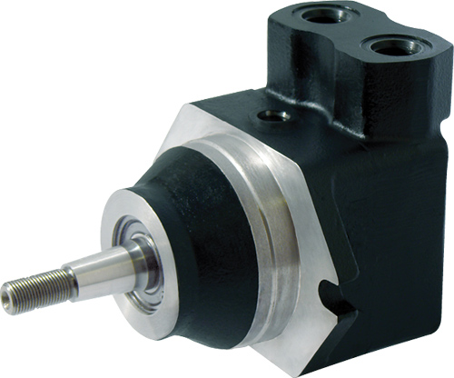
Vane motors are typically classified as HSLT units. However, larger displacements will fall into the LSHT range. Hydraulic fluid enters the motor and is applied to a rectangular vane, which slides into and out of the center rotor. This center rotor is connected to the main output shaft. The fluid being applied to the vane causes the output shaft to rotate.
Parker’s vane motors feature a balanced design where the inlet and outlet ports of the motor are applied to sections of the vane cartridge that are 180° apart from each other to ensure that the hydraulic forces are always in balance inside the motor. Key features include:
• low noise level
• low flow pulsation
• medium pressure
• high torque at low speeds
• simple design
• easy versatility
• vertical installation friendly
They are used in both industrial applications, such as screw-drive and injection molding, and mobile applications such as agricultural machinery.
Piston motors come in a variety of designs with both LSHT and HSLT classifications.
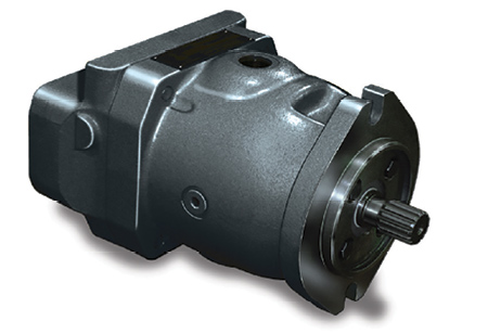
In-line piston motors are classified as HSLT. Hydraulic fluid enters the motor and is applied to a series of pistons inside a cylinder barrel. The pistons are pressed against a swash plate, which is at an angle. The pistons push against this angle, which causes the rotation of the swash plate that is mechanically connected to the output shaft of the motor. The swash plate can be a fixed or variable angle. Variable angle motors can have their displacements adjusted between a maximum and minimum setting. The command signals to change the displacement can be electrical, hydraulic or a combination of both.
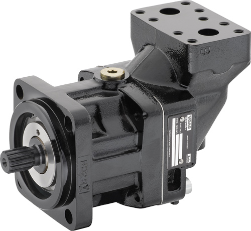
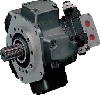
Bent-axis piston motors are classified as HSLT. They are similar to inline motors except that the piston barrel is at an angle in relation to the swash plate. Hydraulic fluid enters the motor and is applied to the pistons, which are contained in a cylinder barrel. The pistons are at an angle to the drive shaft, which means that the piston will rotate the shaft as fluid enters the motor.
They can be both fixed and variable displacement. In a variable-displacement bent-axis motor, the cylinder barrel is rotated between maximum and minimum displacements. The command signals to change the displacement can be electrical, hydraulic or a combination of both.
They are best known for high performance, high pressures, high speeds and volumetric mechanical efficiencies in the 97 to 98% range. The also offer quick reaction and precise control. These motors are suitable for applications that require a significant amount of power. They are used to drive mobile and construction equipment, winches, ship-cranes and all kinds of heavy-duty hydraulic equipment for offshore and onshore operations.
Key features of in-line and bent-axis piston motors:
• higher speeds
• higher efficiencies
• can be fixed or variable displacement
• multiple controls to adjust displacement
• wide range of speeds
• high power density
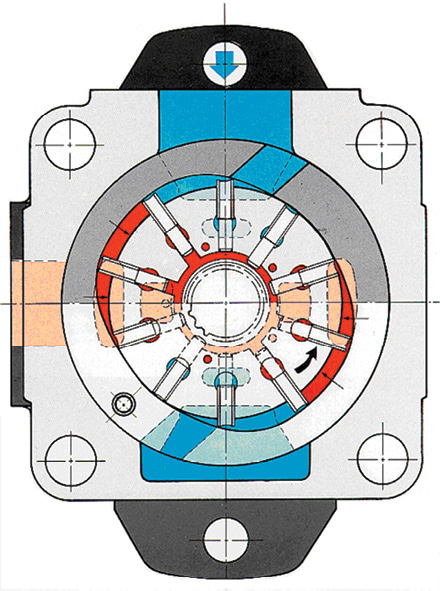
Radial piston motors are LSHT classified. These motors are designed with pistons arranged perpendicular to the output shaft. Typically, the pistons will ride against a cam, which is mechanically connected to the output shaft. The pistons will force the cam to rotate as hydraulic fluid enters the motor.
These motors are capable of producing high torques at low speeds, down to half a revolution per minute.
Applications include caterpillar drives of dragline excavators, cranes, winches and ground drilling equipment.
In general, these motors are fixed displacement. However, some versions will allow for variable displacement. They accomplish this by limiting the number of pistons that can receive hydraulic fluid. Other versions change the internal geometry of the cam the pistons are acting against.
Key features of radial piston motors:
• higher output torques
• lower output speed
• smoother output speed at low speeds (no “cogging”)
• simplification of system design by reducing or eliminating gearboxes or other mechanical ratios that would need to be used in the system
Motor selection considerations
All of the following questions are important to answer when selecting a hydraulic motor:
• What are the performance needs of the application?
• What is the load and amount of break away and running torque needed?
• What is the shaft speed and horsepower?
• What is the operating pressure and flow?
• Is displacement fixed or variable?
• What is the operating temperature?
• Is there any leakage potential?
• What noise level can the application handle?
• How reliable is the motor design?
• What type of controls will be used—mechanical or electronic?
• Is ease of installation critical?
• Is ease of maintenance necessary?
• What is the bearing type and expected life?
• What is the expected motor life?
• Is it open or closed loop?
• What kind of contamination potential is there?
• What certifications and approvals are needed?
Proper hydraulic motor selection starts with the expected performance required by the application, then works back to the prime mover—the pump. Then it is necessary to evaluate the cost of your motor options along with the degree of complexity you want for the overall system.
Parker Hannifin
parker.com
Thanks for the wonderful data.
I would like to connect two hydro motors in series to maximise the torque output.
Can you please give your suggestions.
There is a set of two numbers that rate the viscosity of oil. It is usually accompanied by a “W”. The two numbers help identify the viscosity of the fluid at high and low temperatures. Like the article says, the type of oil you choose depends on the performance application. If it is expected to have a lot of motion, a different oil would be required from an application with less movement.
I’m building a little track drive vehicle it will have a bucket. It is going to weigh 700lbs. I’m looking for 5 -10 miles a hour out of it tops. Looking for more low end power. You’re info was great I’m just new to hydraulic and I’m looking for a little help with selecting a hydraulic pump and motor
Track 136″X6″
Weight 700 -900
Top speed 5 – 10 mph
John, need significantly more data to size pumps and motors. ie wheel diameter, incline or hill climb capability, etc. But try parker P1 pumps:
http://ph.parker.com/us/en/p1-medium-pressure-mobile-pumps-4060-psi-variable-18cc-to-140cc-1
and Parker TL motors:
http://ph.parker.com/us/en/torqmotor-tl-motor-is-a-shortened-version-of-our-workhorse-tg-series-motor-wheel-motor-version-only
Both are already been done for transmission you would look the biggest name in lawn garden transmissions…..Hydro gear.The guys that do 0 turn mower drives. Ag equipment drive all the way out to about 75hp like you see mowing golf courses.
On the bulldozer part I would look at the Struck Tractor co that does bulldozer kits.They have been doing bulldozer kit since the 60’s.Some of the 0turn mower guys use some of their parts to build light duty snow plow attachments for thier 0zero turn.There even track kits that bolt onto wheel bolt pattern of the 0turns..For light duty compact tractor work…..
I need a hydraulic motor to turn a savage pecan tree shaker. torque is 240 lb/in. need 1000 rpm. powered by a 910 cat rubber tire loader I have 29.6 gallon per min @2200 psi. control valve is manual. I would like for the machin e to slowly stop after lever is released.
I have an 8 ft. X 20 ft. swim platform. There is an aluminum leg on each corner to lift it above the water. Each leg has it’s own hand winch. I use an electric drill to lower the legs but they do not have enough torque to lift the platform but almost. I wondered if a twelve volt electric hydraulic system with an orbit motor would do the job? What system would work best for me? Thank you.
I’m looking to build an articulating garden tractor and am planning on running 4 wheel motors with a 23in. Tire. I would also like to operate a 3pt. Hitch from it, no pto. What size pump should I use to achieve 8mph? I want the pump to be able to run the steering ram as well.
I am developing a non – entry tank / pipeline cleaning tracked ROV that will be breaking the accumulated slurry / sludge in the tanks and pipelines..The ROV must have a capacity to run for approximately 6 hours shifts.
The ROV must be capable of handling 5700 pounds ( including self weight of the ROV skeleton , tool head , pump and instruments of more than 3000 pounds approximately
The ROV must be capable of dragging along with it the high pressure water jet nozzle hose that is used to break up the solidified sewage and also must be able to drag the 4 inch suction hose that is mounted on it and is connected on one end to a suction cum jetting cum recycling machine.
The ROV must be able to ROVE at mostly 20 km/ hour speeds on surface as well as in the sewage pipelines.
Please guide me as to how do i get the hydraulic motor sizing done that will power and propel the ROV.
Wow what a great discussion you all have going on system design! Might I suggest you take such conversations to our forums as well, where we are trying to build a community of users like you all to join in system design and troubleshooting discussions exactly like this one?
Please feel free to join here: https://forums.fluidpowerworld.com/index.php
Thanks for reading!
My undeestanding of fluid power. Is vague and limited at best.
I have a winch with a 40:1 gear reducer. I need to pull oak logs from 2400 lbs to 3200 lbs up a slight incljne (4′ in 50′) on a dead pull.
Speed is not a primary concern, only that I can pull the logs.
From that data, my assumption is that I need 60 to 80 lbs of force to move the logs.
Based on that data, do you have any design suggestions?
i have a winch powered by the boom motor on my pile driver barge. the motor cannot lift the piling without dying out. I wanted to power the winch separately with a hydrualic motor which can lift 3,000 llbs. Any suggestions.
Nick
Hello
I need to know the size of pump to run a hydraulic motor that requires 100 l/min at 350 bar. Motor speed is 1750 rpm and Motor power is 65 KW
What type and size hydraulic motor would be best used for a hydraulic chain saw?
I am considering replacing a 15HP 720RPM electric motor which drives a lift pump (which will run continuously). I will use a tractor hydraulic pump to provide >15gpm at >1500#.
Is this a reasonable idea? Could you recommend a motor which might fit this application?
Have a 301.8 cat mini excavator-would like to build a small brush hog. Only have 8 gpm on aux hydraulics. Is there a motor available that would work for this.
Yes look up geroler motors somewhere around 60 cc displacement should work fine
can i replicate a hydraulic motor’s torque speed characteristics with an induction motor?