 Mobile hydraulic machines are the unsung heroes of the world, literally digging the trenches and taking abuse as they fabricate for us the asphalt and concrete world we take for granted. The extreme weather and extreme demands are waylaid by machines performing at extreme levels. That an excavator, skid steer or farm tractor can perform at such a high level for extended periods in the worst conditions is an absolute marvel of modern engineering.
The unique demands on mobile machinery require no stone left unturned when it comes to the design and engineering time put into them. There are tradeoffs which must be balanced accurately between performance, reliability, efficiency and cost, and it’s an unfortunate reality that one of those factors often displaces the others; you rarely get all four.
To ensure a mobile hydraulic machine performs optimally, regardless of cost, intelligent design of the hydraulic fluid conditioning system must be a priority. Keeping hydraulic fluid clean, cool and dry will ensure reliability regardless of its level of performance or efficiency. The first tool in well-conditioned hydraulic fluid is the reservoir.
 A hydraulic reservoir performs many duties of which you may not be aware. It’s obvious the primary function of a reservoir is to hold the hydraulic fluid used to circulate into the actuators of the system, via the pump(s) and valve(s). However, if this were its sole purpose, it would only need to be large enough to hold a volume equal to the differential volume of all the cylinders. Although textbooks may call out for reservoir volume three to five times the flow rate of a pump, this is a pipe dream for mobile hydraulics, so typically they are much smaller than ideal.
Cooling considerations
The reservoir, often just called the tank, also provides significant surface area for cooling of the hydraulic fluid. You can imagine a 50-gallon steel box with 150° F liquid inside will radiate a fair amount of heat, even if airflow was minimal. Of course, cooling capacity depends upon the differential between hydraulic fluid temperature and ambient air temperature. And herein lies the challenge with mobile equipment; the machines themselves create extensive heat, and that heat can make it hard for a reservoir to radiate anything, sometimes even absorbing that heat.
Although engines are often surrounded by protective shrouds and panels, which provide some barrier to contain the heat, it’s often prudent just to mount the reservoir away from the engine and exhaust components. On truck mounted hydraulic systems, this is relatively easy to do, as not often engine or exhaust components are mounted aft of the transmission.
Mobile reservoirs are smaller, so regardless of mounting location, they have less surface area to radiate away heat. It makes me wonder why mobile reservoirs aren’t all made from aluminum cast with integral cooling fins, but then I remember how cost comes into play for mobile machinery. The cooling fins still wouldn’t provide enough cooling, so forced air coolers are used in most mobile hydraulic applications to provide the necessary oil cooling. However, cooling problems aren’t the only consideration for mobile hydraulic reservoirs.
Rivers and baffles
A reservoir also gives fluid time for both air bubbles and particle contamination to settle out, but a smaller reservoir provides less of that time. If an industrial reservoir sized five times the pump flow will provide five minutes of settle time, a mobile reservoir sized twice the pump flow will provide only two minutes before that fluid is sucked back into the pump.
Because of the reduced dwell time, reservoirs must be designed effectively to prevent fluid from rivering from the return line to the pump suction line. Rivering is detrimental because fluid recirculates to the pump without first being conditioned; air, water or particles are not given time to settle out. Adding a baffle—or series of baffles—to a reservoir can provide a couple advantages.
The first advantage of the baffle is fluid is given more time to cool before entering the pump again. The baffle is a plate or internal shape added to the reservoir to force fluid to travel a longer distance to reach the suction port. Because the baffle forces fluid to remain in the tank longer, more time is given to settle out water and particles, and also to allow air bubbles to rise out of the fluid. This is especially effective when the return line enters high in the tank, and the cutouts in the baffle are low in the tank.
Conditioning the fluid
Another purpose of the reservoir is that it provides ideal pump inlet conditions. Aside from closed-loop hydraulic systems, which use charge pumps to force fluid into the pump, it’s not ideal to send fluid right from the system back into the pump inlet. With filtration, cooling and deaeration occurring prior to pump suction, all fluid entering the system is once again clean, cool and free from bubbles. Hot, dirty oil can regenerate itself exponentially for two reasons; hot oil is less viscous, causing more internal leakage, which itself creates more heat. The second reason is that dirty oil is like a lapping compound, exacerbating component wear.
Ideally, your hydraulic machine will employ a kidney loop for filtration and cooling, which less disturbs fluid entering the reservoir, and provides the second benefit of more time for cooling and filtration. A DC electric circulation pump can cool and clean fluid even when the machine is off, just as a modern car’s electric water pump can keep a modern car cool even after it’s shut off. Because a kidney loop system can be thermostatically controlled, it doesn’t waste energy by cooling in cold weather or low temperature start-ups.
Other considerations
Aside from fluid conditioning difficulties related to mobile hydraulic machinery, size and weight limitations must be considered. Mobile machinery has a twofold disadvantage when it comes to choosing a reservoir, in that size and weight are priority considerations. Some machines simply have no large real estate to put a giant cube, and any excess weight reduces payload and increases fuel consumption.
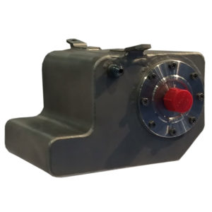
Although the size of a mobile reservoir can be offset by efficient cooling and filtration, sometimes a big cube is just plain hard to place on a tightly buttoned machine. Engineers of mobile hydraulics can employ various techniques to save space with a fluid reservoir. One such technique is to use the machine itself as the reservoir. A structural steel channel can be fitted with the ports for suction and return lines, or even the top cut-out to accept a drop-in filter assembly. This technique saves both space and weight, since no more extra raw material is needed for the job.
Not all machinery is built with channels of steel, so taking advantage of advanced material construction allows compound reservoir shapes to be effective at reducing space. A hard plastic reservoir can be blow-molded into a compound shape that can be fit amongst several other components. Not only does it remove the limitations of a rectangular steel reservoir, it allows mounting amongst other components that would typically be in the way.
Using a molded plastic reservoir also saves weight. A 50-gal plastic reservoir can still easily be lifted with one hand, compared to a steel unit weighing many more times that. Even more cutting edge is the carbon fiber reservoir. Although they could be in any shape, just as a plastic unit, they’re often built as lightweight cylinders, mountable anywhere alongside other components. Not only are these tanks lighter still than plastic reservoirs, they’re stronger than steel. For some mobile machinery, and especially with Tier IV emissions restrictions, every ounce of excess weight counts. Although neither plastic nor carbon fiber transfer heat efficiently, they’re effective on machines already employing a cooler.
Mobile machinery is unique in its design and implementation of hydraulics, with many components and circuits used only in conjunction with internal combustion prime movers. The mobile reservoir is not exempt from these unique requirements, so considerations other than fluid conditioning must be factored.


