Part 1: Taking a methodical approach is the best way to get off-highway equipment working again, quickly and safely.
Read Part 2 of this article here.
By Carl Dyke, Contributing Editor
It is inevitable that even a well-designed mobile hydraulic system will malfunction at some point. There are many reasons why it might happen. Contaminants in the fluid may be interfering with normal component functions. The machine may have been used beyond its design limits at some point. Regular maintenance may have been overlooked or a component such as a pump may have been operated past its expected service life. One component in the system may turn out to be less durable than expected by the designers. These are just a few of the common reasons for system faults.
Once a mobile machine is no longer functioning normally, it is common for the next branch of activities and decisions to become quite abnormal or even suboptimal. In this two-part article, we’ll look at how a typical troubleshooting cycle might progress from beginning to end, how it might become quite random and inefficient, and how it is possible to stay organized and on-track.
Operator’s complaints
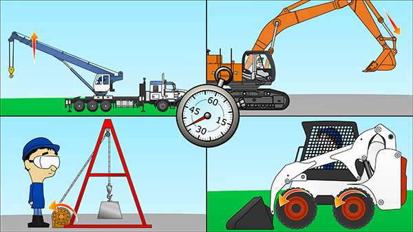 Troubleshooting will likely start after a complaint from the machine operator. The operator may notice that functions have become slow. Maybe it’s the boom lift on a crane, or the bucket curl function on an excavator. Perhaps winch speed or travel speed has become slow. Another potential problem is that a cylinder or motor is moving too quickly. These are problems related to the rate of flow.
Another type of complaint is a problem with lifting the heaviest of normal loads. The cylinder or motor motion for the lift function stalls completely under these loads. If the machine has hydraulic propulsion at the wheels or tracks, the equivalent fault would be stalled motion on steeper slopes—ones that can usually be climbed without difficulty. Instead of a complete motion stall, the issue might be an uneven, hunting motion at the cylinder or motor. These types of complaints often point to a problem achieving pressures in the normal, maximum range.
 Another range of faults might include one machine function that will not operate at all, or perhaps the cylinder will move only in one direction. A final example is a hydraulic motor or cylinder that is creeping or in full motion when the controls are placed in neutral/hold position. These issues are often thought of as directional problems.
We have described a range of faults in three different categories, any of which would frustrate a mobile machine operator who was expecting a normal day at work. The temptation for some troubleshooters under downtime pressures might be to go deeply into the heart of the hydraulic system, replacing a pump or a main valve. That would be jumping far ahead in a process that needs some thought and care. A methodical process will usually consume less time and will avoid needless component replacement.
The technician as investigator
So, how does a troubleshooter start the process? Start with the operator who filed the complaint. A shop technician might receive a work order with a simple description of the fault. The complaint may not be described as clearly as the earlier examples. Hours may have elapsed since the machine was taken out of service. Find that operator if possible and ask questions.
This is a great time to adopt crime scene investigation skills. You’ll want to ask the operator to explain the fault. Let the story emerge naturally, but interrupt when you need more specifics, such as what type of material was being excavated, or whether the load to be lifted was a usual and normal load. If the operator uses a vague word such as “sluggish” to describe the malfunction, you will want to ask exactly what is meant by that word. You’ll want to know if the problem just happened suddenly or were there other symptoms leading up to the fault in the preceding hours or days. Did the fault occur when the machine was cold at startup, or did the problem only appear once the system was warmed up? Did the operator notice that the hydraulic system was running warmer than usual? Ask if the operator can remember anything else out of the ordinary leading up to the fault. Be patient with this process, listen carefully and take notes.
 If the operator reported that his track-driven machine could not climb an uphill grade of considerable—yet normal—steepness, and then you find a low/high travel speed switch in the cab set in the high speed position, you might decide to test the machine yourself or call the operator back to see if perhaps he just overlooked a setting (high-speed travel) that is not meant to work for steep slopes.
What is happening at this stage is called confirming the fault. It is not always possible for a technician to do this easily, once a massive piece of equipment is parked in the shop. If possible, visit the machine on-site soon after a fault is reported so that the symptoms can be witnessed first-hand, and to have the operator’s involvement in the testing. The efficiency of teamwork and trust is valuable in this process.
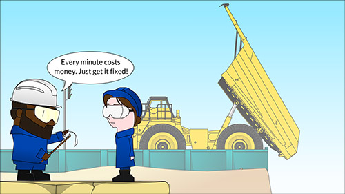
In some situations, the faulted machine has to be repaired at the job site. The failure will be holding up the progress of work. If, for example, a crane has lowered a load into position on a construction site but cannot lift the hook (hydraulic winch) after being detached from the load, there may be psychological pressure on the troubleshooter to work quickly. The same will hold true for a mining haul truck that is stuck at the dump station with the body hoisted and with no lowering function. A troubleshooter will most assuredly be asked shortly after arriving: How long will it take? This makes for challenging working conditions. In this type of situation, it becomes easy to overlook simple causes for the fault. A troubleshooter must take control of the process and take the time needed to gather important clues and information.
The reason to take the time to gather clues carefully is because it is difficult to know exactly what is going on inside hydraulic components at the time of malfunction. Detailed component testing is time consuming and can be difficult to do safely on-site. Resorting to guesswork component replacement uses up both time and money. What you are trying to do is to gather as many clues from the outside of the system as possible. Some of those clues may be subtle.
Initial diagnostics: Look for simple causes first
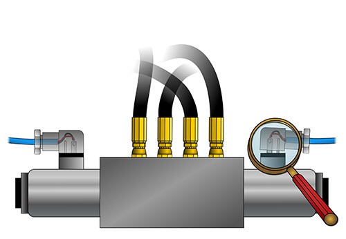 Most technicians would agree that it is easier to test electrical systems than hydraulic systems. Safety procedures are still needed of course, but a good quality electrical multimeter can quickly test the internal values of most electrical components at the exposed wiring terminals. Testing related electrical functions on a hydraulic system is one of the tasks you’ll want to carry out sooner rather than later.
Note: In all cases of live hydraulic and electrical testing, be sure to follow all of the machine manufacturer’s safety recommendations. You should already be trained in safe hydraulic work and testing procedures.
 But let’s start with even easier, simpler tasks. Of course both operator and technician must always be on the lookout for an external leak. This is the level of simple diagnostics at the beginning of the troubleshooting process. Vibrations can cause some valve solenoid connectors to work loose. Noticing a loose connector or a wire that has become disconnected makes for a short, simple, inexpensive troubleshooting cycle.
If the complaint is numerous slow functions and erratic motions on the machine, and strange pump noises, a technician may want to check the fluid level in the main hydraulic tank. It might be quite low, causing serious flow problems when the machine is working on sloped ground. When were the filters last serviced? Is there a layer of foam on top of the fluid in the tank indicating air ingression? The spongy, non-positive cylinder motion might just be a clamp on the pump suction hose that has come loose, allowing a lot of air to be drawn in. If these points seem obvious, then this is just encouragement not to jump to conclusions too quickly with a decision to change out the pump. Easy-to-check items and issues are often overlooked by great troubleshooters only because of psychological pressure from those waiting for the machine to be fixed.
Schematic diagram as battle plan
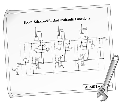 If there is no obvious external clue to the malfunction as reported and confirmed—and if a technician has not encountered a particular fault previously—a deeper, more rigorous troubleshooting process must commence.
Don’t bring out the test gauges and flow meters just yet. It’s now time to make a battle plan. The schematic diagram is the most useful tool for planning and guiding troubleshooting work.
In the case of an open-loop circuit, there may be a number of parallel flow paths from the tank out to the pump(s), onward to the directional valves, then to the actuators, and eventually back to the tank. On any one of those main flow paths, there will be valves and other components in series (filters, check valves, flow controls, pressure reducing valves), and there will likely be additional short parallel paths (branches) back to the tank through pressure relief valves.
The schematic diagram is a master flow routing plan, showing the reader where fluid is meant to flow for the different functions, and at different stages of operation. The whole hydraulic system is essentially a circuit, with sub-circuits and then components. The component symbols are drawn in their normal state as though the machine is shut down. A troubleshooter needs to know the language of the symbols so that she can animate those symbols (for example, shift a directional valve) in her mind’s eye, and study the circuit and sub-circuit flow paths for different stages of machine operation.
The schematic also allows the technician to think about where fluid might flow internally, where or when it should not be. A piston seal that fails, or a check valve that will not close, may create an internal leak and be responsible for diverting some or all of the pump flow back to the tank. It is hard to see these possibilities when just looking at collections of hoses, fittings and components on the machine. Mobile machines pack a lot of hydraulic functions into a small space, making it hard to follow and lay out the machine circuit just by looking at hoses and the many strange blocks of steel that they are connected to.
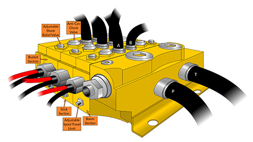 Manifolds are large blocks of aluminum or steel that may have components inserted deep inside, under covers or a plug. They may also feature threaded cartridge valves with part of the component visible from the outside. Valves may also be mounted right on the surface of the manifold. In many cases, manifolds contain all three types of components, making a schematic vital to any real understanding of the circuit. Sectional valve banks that are common to many mobile machines also contain a number of additional components in each directional control section.
CD Industrial Group Inc.
carldyke.com
LunchBoxSessions.com


I like the article, it covers all the initial steps of troubleshooting – and I have been many times in this situation. I am looking forward to read part 2
So true, few simple rules and guidelines can make troubleshooting much more easier especially in the field and under pressure. Nice article Carl. I hope to get more training from CD Industrial Group in future.
This article does provide a useful insight, especially about gaining a description from an operator. Third-hand descriptions of a problem can lead to showing up to do a repair with totally the wrong parts and tools. But, I would suggest a check of the fluid tank level as an “almost always” very first step because it is simple, easy, and can reveal a number of problems immediately.
Congratulations Paul! Excellent Post!
whats wrong when the boom doesnt go down?
What is the difference between an open hydraulic circuit and a closed hydraulic circuit?