
Taking a methodical approach is the best way to get off-highway equipment working again, quickly and safely.
By Carl Dyke, Contributing Editor
In Part 1 of this series, (http://goo.gl/Iq3cKb)we examined how to diagnose a problem, look for simple root causes, and use schematics as guides. Now, let’s get into a real-world example that you could encounter.
Example: A small excavator with slow bucket curl
Starting with troubleshooting, let’s say that just one function, a cylinder, controlled by its own directional valve is unusually slow while extending and retracting. Other cylinders on separate directional valves, in parallel sub-circuits, are working normally. We’ll say that the unusually slow cylinder function provides bucket curl motion on an excavator, and that the boom and stick cylinders are working fine. This sounds like a flow rate problem for the bucket curl cylinder sub-circuit.
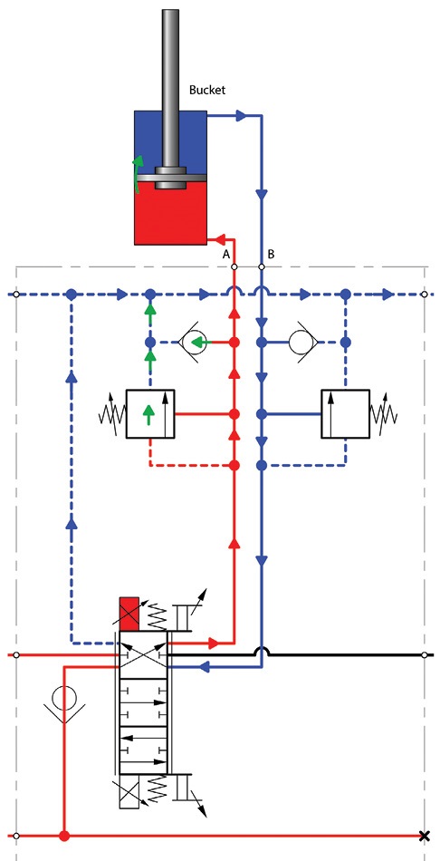
The schematic (found on page 48) helps us see the sub-circuit components for the control of the cylinders. They are all fed a supply of hydraulic fluid from the same “P” line (red) inside the valve manifold. The directional valves all exhaust to the same “T” line (blue) that is routed back to the tank. Each directional valve provides variable speed (proportional flow) control for cylinder extend and retract motion. The proportional directional valves are operated by variable current solenoids.
The directional valves feature adjustable screw stops that limit the maximum travel of the valve spool in each direction, limiting flow rates.

Each cylinder sub-circuit also features a shock relief valve on the lines between the work ports and the cylinder. These valves limit the pressure in a cylinder and its A and B hoses when external forces are acting against the cylinder, while the directional valve is in neutral (A and B ports blocked). Shock relief valves are typically set to the highest pressure of all the pressure controls in the hydraulic system. A pair of anti-cavitation check valves are also present to provide makeup fluid to the cylinder on the opposing port from where a shock relief action may have occurred.
The technician reads in the manual that it is a single, variable-displacement, pressure compensated pump that provides flow for the three cylinder functions. The pump is a bit oversized in comparison to the size of the directional valves, and therefore large enough to provide flow for all three cylinders to be operated simultaneously. While the maximum speeds of the cylinders vary somewhat depending on whether they are being operated alone or simultaneously, the operator has noticed that the bucket curl cylinder is now very slow even when used alone.

Having confirmed the fault and noticing no external leaks or any other obvious clues, the technician studies the schematic to confirm the flow paths that are meant to exist, and to look for others that might come to exist if there was internal leakage. The technician is also looking for any other component that could cause unusually slow travel of the bucket curl cylinder.
The technician observes that the flow through the bucket curl directional valve could bypass to tank through any of the shock relief valves or anti-cavitation check valves, if one or more of them were to stick in the partially-open position. An internal leakage path could also exist if the piston seal in the cylinder was failing. Any and all of these internal leakage paths could account for a slow bucket curl cylinder.
If the technician starts to plan various tests for internal leakage using flow meters or hand pumps, is she getting a bit ahead of herself? Quite possibly, yes. One of the clues was that the bucket curl cylinder was slow while extending and retracting. If the shock relief valves and/or the anti-cavitation check valves were to be the prime suspects, more than one of them (at least one of two, on each of the two main work lines to the cylinder) would had to have failed simultaneously. It’s possible of course, but not as likely as a failed piston seal which, as a single component failure, could affect both directions of travel.
The technician decides to do further checking in the machine manual and notices that the piston in this particular cylinder has one seal for extend, and another separate seal for retract. Both seals must have failed to cause the problem as observed. The technician wonders what she might be missing.

Noticing the adjustable spool travel stops on each valve section—which allow for the maximum opening of the valve to be limited—the technician decides to look closely at the adjustments. It doesn’t look like anyone has made any changes to the settings as the paint on the adjustment screws and jam nuts have no scuffs or chips. The technician checks the manual to see if there are any notes about the normal position or thread length of the adjustment screws and finds none. There are only maximum flow ratings from the A and B work ports to the cylinder. Checking those flow ratings would require flow meters and a fair amount of time to install them.
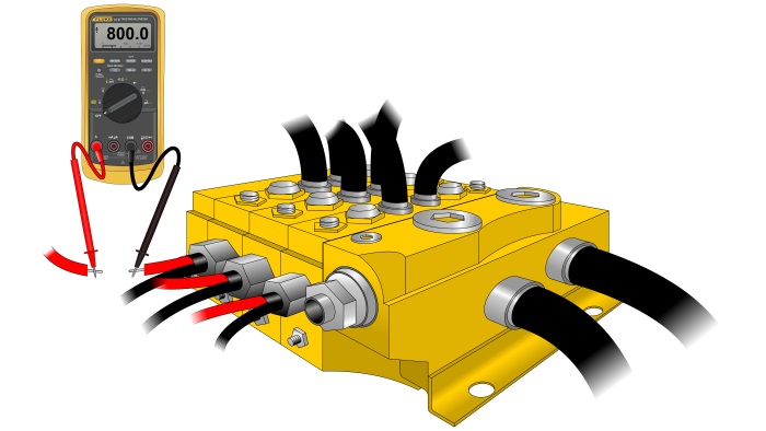
The technician decides to check the electrical signal to the solenoids, as seen on page 46. The directional valves are proportional valves that can vary the flow rate to the cylinder, depending on how far the operator moves the control stick. This means that the valve solenoids receive a signal that is more sophisticated than just an on-off voltage. The best way to test the drive signal as specified in the machine manual is to measure the range of dc current on one of the two conductors for each solenoid. The manual specifies that the normal solenoid current for the range of motion on the operator’s control stick is 0 to 800 mA.
The test for each solenoid doesn’t take long, and it is soon confirmed that the electronics and electrical system for the valve is working fine. The technician had assumed that if for some reason, the machine’s electronic controller was only sending up to, say, 400 mA maximum to each solenoid, that the problem of a slow cylinder would be due to a proportional directional valve that was not being driven correctly to achieve the full and normal flow rate.
One last external examination of that valve bank reveals a clue that the technician hadn’t noticed yet. There was a bit of scuffing on the jam nut for one of the two shock relief valves in the bucket curl section. It appeared as though just one of the two shock relief valves had been adjusted by someone. The technician wondered if this change could have anything to do with with the slow bucket curl in both directions. It didn’t seem likely, but the matter still needed investigation.
The technician called the operator and asked if anyone had worked on the unit or made any changes to valve settings in recent days. The operator told the technician a story about needing to hoist some concrete blocks across a ditch. The lifting chain had been attached to the bucket teeth with the bucket curled all the way inward. The operator would leave the bucket curl valve in neutral (A and B ports blocked) and just lift the boom and swing the block across the ditch. Some of the blocks were so heavy that the bucket cylinder moved inwards during the lifting. The chain would then fall off the teeth and the block would drop. The operator had been told by another operator of a similar machine that he could just increase the setting on that one shock relief valve by a full turn or two, and that the bucket would then stay in position and not curl outward while lifting.
The technician realized that this dangerous action by the operator was subjecting the bucket curl’s sub-circuit to harsh treatment, but still couldn’t quite understand how this one valve adjustment might have caused the problem of a slow bucket curl in both directions of cylinder movement. The technician followed a procedure in the manual to reset the shock relief valve to the correct setting and kept on thinking. While looking at the extended rod of the bucket curl cylinder, the technician began to wonder if she was seeing a slight bend in that rod.
After confirming with a straight edge that the rod for the bucket curl cylinder was indeed bent, the technician realized what had most likely occurred. The shock relief valve that the operator had tampered with was the one for the “A” port, protecting the blind (base) end of the cylinder. While lifting with the bucket locked in position, the excess weight was essentially forcing the piston against a body of trapped fluid in the cylinder. With the rod fully extended, and the shock relief taken out of action due to the operator adjustment, the excess weight was flexing the bucket and making the cylinder rod bend. It was now permanently bent, which was accounting for an unusual level of friction for the cylinder as the rod was moved in either direction.
Repair and further analysis

The repair solution was simple—install a new cylinder and note with a bold warning on the work order that an important valve, a shock relief valve, had been adjusted upward from its safe and proper setting by an operator, resulting in a bent cylinder rod.
With the machine verified to be back in normal working order on the job site, the next logical step for a machine owner and the technician is to think of what might prevent this problem in the future. In this case, the options included dealing with operator work procedures and policies, and/or asking the machine manufacturer to install tamper proof shock relief valves.
Troubleshooting is our primary subject in this article, so let’s continue with an analysis of the procedures followed.
What the technician did correctly was to avoid any rushed component swapping. She also avoided conducting time consuming tests until she had exhausted all possible simple causes, and had visually scoured the hydraulic system for external clues.

If anything, the technician could have spent even more time talking to the operator back at the beginning, to try to get the full story about everything that had recently happened. There is of course, no guarantee that the operator would have shared all of the details up front.

The technician took the time to study the schematic carefully and interpret the circuit features. She anticipated where internal leakage paths could occur, and used logic to determine that multiple simultaneous faults were not as likely as a single, simpler cause.
With the boom and stick cylinders operating at normal speed, even when used in combination, the pump was an unlikely suspect component. If the complaint was that all machine functions were operating slower than normal, the pump would have made it onto the suspect list.
Achieving “battle readiness” for next time
As mentioned earlier, troubleshooting activities can use up a lot of time. This is especially the case when diagnostic instruments such as flow meters have to be installed. Half the battle in efficient and effective troubleshooting is knowing exactly what “normal” is.

Regular maintenance checks should include cylinder cycle times, so that a complaint of a slow cylinder can be understood in the context of optimum machine performance. When a new machine model is brought under a technician’s care, she might choose to measure the thread length on the adjustable spool travel stops, or the number of turns outward from highest (closed off) setting of the shock relief valves. Observing the machine running normally on the job site can yield valuable references for detecting the less than optimal performance that may precede a breakdown.
Taking careful note of normal pressure values, component temperatures and the normal whistling sounds of fluid passing through valve components can help locate an important clue when the machine begins to malfunction.

As is so often the case, a sudden malfunction can have a simple cause. It is possible for that simple cause to be buried deep inside a pump or a valve bank. However, with keen investigation, observation and analysis skills, a technician will be able to find the simple causes that are accessible from the outside of the system.
Lessons Learned:
• Get a complete story from the operator
• Confirm the fault
• Look for any obvious external clues (leaks, discolored paint, etc.)
• Consult the schematic to plan
tests logically
• Avoid guesswork (part swapping,
experimental settings changes)
• Keep looking for simple causes
• Verify the repair
• Observe and record normal operation
• Improve maintenance and battle plan
CD Industrial Group Inc.
790 elc john deer pumps making full pressure going over both main reliefs when no functions are used. mane valve spool are not sticking. pumps seem like in full stroke
need help from a hydraulic specialist on a sy205c excavator
I have an excavator 330d with slow swing speed problem. The pressures at right/left swing relief valves are supposed to be between 28000 to 32000kpa according to the caterpillar specs. I have checked my pilot pressure and it’s on specification which is 4100kpa, however when adjust the swing relief valves they don’t get their specifications even when they’re adjusted to maximum, they only get between 22000 and 24000kpa yet the swing speed remains slow. I have replaced the hydraulic oil filters. I even removed the pilot pressure lines to the swing control valve just to verify if there’s oil flow when the swing function is activated either side and the pilot pressure does come with high pressure I should say. I have gone as far as replacing the swing motor, but to avail. Can you assist