Load-holding valves, or counterbalance valves, are simple devices but critical to mobile machine stability and cost.
Contributed by Todd McIntryre, Global Planning and Strategy Manager, SiCV, Eaton
 Load-holding valves, which are also known as counterbalance valves, are a small but important part of any mobile machine. Though they are simple in design, their application can often times frustrate even the most skilled and experienced engineers. Having a basic understanding of load-holding valve operation and how to apply them can allow engineers to improve the stability and reduce cost in mobile equipment.
Why use load-holding valves?
A load-holding valve can provide these basic functions:
- Load holding, which prevents the uninitiated movement of an actuator on a machine.
They are used when a machine requires the boom to remain in one position for extended periods of time. For example, an individual using a cherry picker to per- form work on utility lines would be frustrated were the boom to drift downward. The poppet design of a load- holding valve limits the movement to almost zero. This gives the worker confidence that they can complete their work without boom drift. - Load control provides a counterbalance when lowering a load. It can prevent the actuators from running ahead causing uncontrolled movement or pump cavitation.
When lowering a load it is important that the operator maintains complete control of the actuator. For example, when lowering a pallet of bricks with a telescopic handler the load will accelerate with the assistance of gravity and potentially become unstable. A properly applied load-holding valve can prevent this from occurring. - Load safety prevents uncontrolled movement of an actuator in the event of a hose failure.
All hoses have a fixed life and are often the first component in a hydraulic circuit to fail. Without a valve positioned and set correctly, a boom or winch could free fall creating a very dangerous situation.
At their core, load-holding valves are an extremely important safety-related device. By helping prevent dropped or uncontrolled loads—whether the load is logs, dirt or even a person—load-holding valves keep worksites safe.
Basic operation of load-holding valves
To easily understand how to apply load-holding valves, it is important to first understand how they work. A very basic hydraulic example is when a directional valve is being used to raise and lower a load vertically.
A standard load-holding valve has been placed between the line running from the directional valve to the rod end of the cylinder. Although known by many different names, a standard load-holding valve can be described as a “pilot-assisted relief valve with a free flow check.”
As the operator raises the load, he or she will direct flow to the rod end of the cylinder. In this upward direction, you are working against gravity and the load will not want to run ahead. For this reason, the flow from the valve will pass through the free flow check portion of the load-holding valve and lift the load by retracting the cylinder.
Lowering the load will present greater challenges as the operator is now trying to move the load in the same direction as gravity in a controlled fashion. With the added acceleration of gravity, the load will have the tendency to run ahead of the control and pump. Without the use of a load-holding valve, the operator may lose control of the load or the boom may become unstable.
A load-holding valve provides the needed control by relieving flow from the rod end of the cylinder. When the operator intends to keep the load still and has the directional control in the closed position, the free flow check will prevent fluid from moving from the rod end of the cylinder to tank and hold the load in position.

As the operator lowers the load and directs flow to the bore end of the cylinder, pressure will be applied to the load control valve through the pilot line. The combined pressure from the pilot on the bore end of the cylinder and the load pressure from the rod end of the cylinder will open the load-holding valve, allowing flow from the cylinder to tank to lower the cylinder.
As the load begins to lower and accelerate, the pilot line pressure will decrease and begin to close the load-holding valve. This prevents the load from running away. With the valve closed, the pilot pressure increases and the load-holding valve will again open, allowing the load to lower in a controlled fashion.
Using a load-holding valve that can meter this flow in a controlled manner is absolutely critical in designing a stable and efficient load-holding system.
Load-holding valves for standard applications
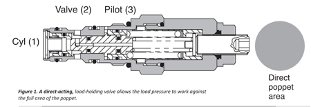
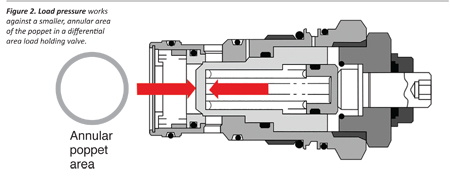
Engineers can meet the requirements in a wide variety of load-holding applications using a standard load-holding valve. However, there are two very different design types of standard load-holding valves on the market. They are known as direct acting, Figure 1, and differential area design, Figure 2.
With each of these designs, the valve has a single poppet to meter flow from the cylinder to the directional valve, and the load pressure works against this poppet. The difference in the two designs, which is critical to boom stability, relates to the spring force required to reseat the valve.
Direct-acting valves, Figure 1, have a large poppet area working against the load pressure. Because of this large poppet area, greater spring force is required to reseat the poppet. This direct-acting design is common among the millions of types of relief valves applied every year in standard hydraulic circuits.
In contrast, a differential area load-holding valve applies backpressure to the poppet that offsets the load pressure and results in a smaller, annular effective area of the poppet. Therefore, less spring force is required to re-seat the poppet.

Spring force is important because it directly affects the stability of the valve. A higher spring rate is an advantage in many applications where unstable loads introduce varying induced pressures. The higher spring rate prevents the valve from reacting too quickly and over-opening, which causes boom bounce or audible instability.
Differential valves, with a lower spring rate, are prone to rapid opening. While this can be advantageous for some higher flow applications, the rapid opening can often lead to instability which results in boom bounce or high pitched squealing. The rapid opening also makes the valves more sensitive to changes in temperature, wear and general mechanically induced friction.
Load-holding valves for highly dynamic machines
For machines with high dynamic loads, such as on a concrete pumping truck with multiple booms, a machine designer would need to look beyond the standard valve. In the example of a concrete pumping truck, heavy concrete is being pushed through multiple booms, changing the loads significantly as portions of the booms are empty or full of dense concrete. Stabilizing these loads takes a more advanced valve.
The machine designer has a couple of choices when presented with extremely unstable conditions—either they restrict the flow or can use a two-stage load control valve where the initial restriction is removed once the movement is stable.
A restrictive valve operates by restricting the opening so the oil has to be driven across an orifice. This is inefficient in that it generates heat and makes it difficult to control the actuator speed.
The two-stage valve creates an initial restriction that is then removed as the valve stabilizes and the pilot pressure increases.
Improving machine design with load-holding valves
Given the importance of these valves in a system to ensure safety and security of operation it is paramount that they are assembled correctly and in the right place on the machine. They also have to be secure in their cavity to prevent loosening or unscrewing. Industry common cavities often have large bearing areas to transmit torque between the load-holding valve and manifold. By using a larger mating surface, the common cavities reduce assembly torque. Higher torque can result in manifold deformation which can generate contamination or reduce security of assembly.
There are a number of common opportunities where choosing the right load-holding valve can make a difference in a new machine. With the right valve, boom stability, productivity and safety can be improved, noise at start up and potential for contamination can reduced and designs can be simplified.
Eaton
eaton.com

