By Josh Cosford, Contributing Editor
Back in August of 2017, you saw my article Hydraulic symbology 101: Understanding basic fluid power schematics (read it here first, if you haven’t already). I covered basic constituent lines, shapes and their respective symbols. Due to space constraints, I left out some of the major components represented by symbols in hydraulics, so here I continue with Hydraulic Symbology 102.
I had previously discussed lines, squares, circles, and diamonds, but I left out rectangles, ovals and oddities. Other than boundary lines, there are few rectangles in hydraulic symbology, especially if you consider a 4/3 valve symbol as three squares (which I do). As it turns out, cylinders use rectangles in three forms.
The basic differential cylinder is a wide rectangle partially bisected by a line being the rod, itself attached at one end to the piston. Although not always necessary, the ports are appointed by stubby lines. This first example is a differential cylinder, meaning its single-rod construction has a differential of both area and volume on either side of the piston. It will extend with more force than it retracts but will retract with more velocity than it extends.
 The ram supplements an additional rectangle to the cylinder symbol, which depicts a large rectangular “rod” instead of the simple line. A ram, by definition, is single acting, so the rod side port is omitted. Replacing the second but adding a third rectangle to the mix is the choice of head and cap cushions. In the symbol shown, the diagonal arrow of adjustability is included to call out some type of needle valve to control cushion rate in the head and cap. The adjustment isn’t within the piston, as appears from the symbol. Hydraulic symbols are functional representations in their simplest forms, so get used to reading them with that in mind.
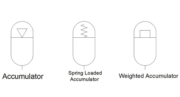
After rectangles come ovals, which are often confused with an ellipse. The oval is oblong with two straight lines, where ellipses are stretched circles. In fluid power symbology, an oval represents an accumulator, or energy storage vessel. Most accumulators are energized with inert gas, such as nitrogen, and the symbol shows a partition separating the top and bottom of the oval. In this case, the top side also illustrates a hollow arrow — it’s telling us there is air involved, and in hydraulics it can also sometimes appear as a pneumatic pilot signal for a directional valve operator.
 Accumulators don’t need gas to supply stored energy, of course, so we can add potential energy mechanically as well. A spring on the other side of oil in a piston accumulator compresses to store energy as air would, although a spring cannot compress as infinitely as gas. The jagged spring symbol is the exact one used in a directional or check valve. Turning the spring into a square signifies we now have a weighted accumulator, which is my favourite type. A weighted accumulator is the only one able to supply continuous and stable pressure as it depletes itself, contrary to the limited and varied pressure and flow available from the other two.
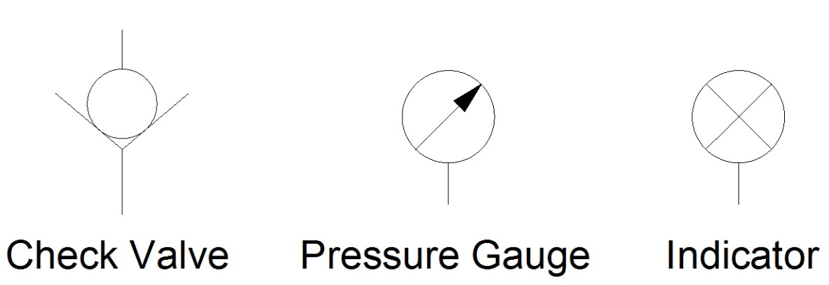
The small circle is next in the hierarchy and portrays auxiliary components important to complete a hydraulic system. The check valve uses a small circle stuffed into a wedge to represent very accurately a chrome ball nested into a conical seat. In our image, it’s easy to imagine flow from the bottom port can lift the ball from its seat and continue to flow around the ball. Any flow from the top port will do nothing but force the ball harder into the seat, absolutely restricting flow.
 Next up are two common ways to identify pressure in a system; the pressure gauge and pressure indicator. The pressure gauge is logical, showing a needle within a circle, making it not hard to imagine the bottom-mount unit most common in our industry. Less intuitive is the simple pressure indicator, with is the same small circle but with a cross through the centre. Pressure indicators are simple devices used to signal a chosen pressure has been reached, such as with the bypass indicator in a hydraulic filter assembly.
For the most part, the common shapes are now spoken for. This is where symbols take on unique depictions unable to be expressed with grade school geometry. A shut off valve is represented by two adjoining triangles. A simple “T” added to the shape highlights your handle, but this symbol has no way of telling us if it’s open or closed.
 An orifice is a generic term to describe an area of fluid travel chocked down to restrict flow. The orifice can be blunt or knife-edged, fixed or variable, and in all honesty, can exist as a ball valve by my above definition. The orifice symbol is a line with two mirrored arcs aside it, appearing to push towards the path of flow, restricting it. A diagonal arrow added to the mix completes the symbol and now shows what we call a needle valve. Note, a flow control valve needs the addition of a reverse flow check, which this symbol does not have.
Finally, these last two symbols represent slip-in cartridge valves, also known as either DIN valves or logic elements. These are fascinating valves capable of so much … directional control, flow control, pressure control, they can do it all. They are 2/2 valves used in large manifolds and controlled by separate pilot valves mounted atop. The complexity possible with logic elements is dizzying, but basically it takes four of these valves just to control a cylinder. I show here both the DIN and ISO versions of the symbol, but explanation any deeper than this could take an entire textbook worth verbiage. That my friends will come in Hydraulic Symbology 501.


