
By Josh Cosford, Contributing Editor
Hydraulic cylinders are available in a variety of styles and can be mounted in numerous ways. Here’s a look at some of the most common options and their advantages and disadvantages.
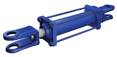
The venerable hydraulic cylinder is the most effective means of creating linear force in the mechanical kingdom. They are efficient and reliable, and although little of their basic design has changed significantly in eons, they are still relevant to the industries to which they cater. Hydraulic cylinders are manufactured to either the standards of their designer or the standards of the geographic bureaucracies of the manufacturer’s continent, such as NFPA or ISO.
Although some cylinders are manufactured with a generally poor build quality, such as with cast iron caps and heads, higher quality cylinders are typically constructed with forged steel. The “welded” type cylinder is very common, and even though the specifications for their dimensions, sizes and rod treatments aren’t part of an industry standard, they are common enough in construction that many manufacturers build them the same way.
The welded cylinder is simply a barrel with a cap welded to the bottom, and then with the mounting treatment welded to that cap, typically a cross tube or dual tangs to mimic a clevis. The piston and rod are installed into the cylinder, and then a threaded head is slid over the rod and torqued onto the barrel. Finally, the rod treatment is added to the cylinder, which is sometimes a cross-tube welded directly to the tip, or if the rod end was threaded, any other rod treatment common to the industry, such as a clevis or a rod eye.
Cast tie-rod cylinders and welded cylinders make up a fair portion of the cylinder market, especially in the mobile equipment industry, but the NFPA and ISO standards for tie-rod cylinders are the most common in any high-end hydraulic machine. The metric ISO standard for cylinders is quite similar to the National Fluid Power Association’s standard using imperial units, except of course for the difference of measuring technique. ISO and NFPA even use the same 3-character alphanumeric code for mounting options, such as MT1 for head trunnion or MP1 for fixed clevis.
For the remainder of this missive, I will refer to standard NFPA and ISO variants as simply tie-rod cylinders. The advantage to the standard tie-rod cylinder is in the modular nature of the parts used to create a finished product, such as the cap, barrel, head and rod sizes, which allow a cylinder to be assembled in a few days from off-the-shelf parts.
Opposite to the rod side is the cap, which is essentially a block of forged steel machined with a deep ring to accept the barrel, which seals with an O-Ring. The cap end is typically very simple, with just a port machined to direct fluid into the piston side, the four drillings for the tie-rods and sometimes a cushion screw. Opposite to the cap is the head, which is more complex and consisting of more parts. Besides the parts mirrored by the cap—the port, the tie-rod and sometimes a cushion—the cap must also contain the bushing, gland and the rod seal package.
The standards for tie-rod cylinder design apply mostly to the mounting dimensions, and less so for the internal design of the cylinder, which can vary significantly from manufacturer to manufacturer. These differences can exist with piston design, head design, rod gland and seal design etc., but the exterior mounting dimensions must remain the same, such as retracted length, clevis pin diameter or trunnion dimensions, if so equipped.
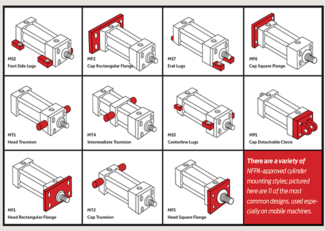
A basic cylinder comes with no end treatments; however, by simply drilling and tapping two threads each in the cap and head, we create the MS4 Side Flush Mount cylinder, just one of many choices. Each mounting style has its advantages and disadvantages, and although there are many options, the most popular choices are as follows:
• MP1 – Fixed Clevis
• MP2 – Detachable Clevis (not pictured)
• MF1 – Front Flange Mount
• MF5 – Front Flange Extra Size Mount
• ME5 – Front Head Flange Mount (not pictured)
• MF2 – Rear Flange Mount
• MF6 – Rear Flange Extra Size Mount
• ME6 – Rear Head Flange Mount (not pictured)
• MS2, MS3 and MS7 – Side Lug, Center Lug and End Lug Mounts, respectively
• MT1, MT2 and MT4 – Front Trunnion, Rear Trunnion and Trunnion Mounts, respectively<
MP1 (fixed clevis) and MP2 (detachable clevis) are one of the most common types of mounting options used, especially in applications where the cylinder must pivot through an arc as it extends and retracts, such as with a boom crane or bin tipper. The fixed clevis is a part of the cap itself—a detachable clevis is bolted to the cap, and both allow engagement to a clevis mounting bracket with a steel pin held in place with cotter pins or snap rings. Clevis mounts require attention when being applied, however, as they are highly prone to side load and column strength issues, which I will discuss later.
MF1 (front flange mount), MF5 (front flange extra mount) and ME5 (front head flange mount) are all methods of mounting the cylinder off of, or part of, the head itself. MF1 has a rectangular flange attached to the head, which protrudes from the sides of the cylinder, and the MF5 has a larger square flange protruding in all directions, which provides extra strength. The ME5, instead of a flange being mounted to the head, uses an extra thick and wide head, which itself attaches directly to the machine. These options require the cylinder to be stationary and this fixed centerline mounting provides them with high column strength.
The MF2, MF6 and ME6 rear flange mounts are similar to the front flange family, except their respective locations are off the cap rather than the head. The MF2 has a rectangular flange attached to the head, but protrudes only on the sides, the MF6 uses the same larger flange as the MF5 and the ME6 has a beefy cap containing mounting holes for direct attachment to the machine. Being fixed centerline type mounts, they offer the same strength advantage of the front flange versions.
The lug mounting options use rectangular tabs machined from the same block of steel as the head and cap, although they are sometimes welded on. The four MS2 side lugs are on the bottoms of the head and cap, the MS3 center lugs are mid way up the head and cap, and the MS7 end lugs are mounted to the front bottom of the head and back bottom of the cap, reaching fore and aft like sphinx paws. Because of the fixed mounting, lug style cylinders are very rigid, although the nature of dual mounting points can add worries of misalignment between the front and rear lugs, especially related to bending or torquing of the mounting surface.
Finally, the MT1, MT2 and MT4 front, rear and intermediate trunnion mounts, respectively, are an alternative to the clevis style pivot. They allow the rod to move through an arc as it extends and retracts, although they have a slight advantage in column strength and precision of movement over a clevis mount, especially the MT1 (front trunnion) and MT4 (intermediate trunnion). The MT2 (rear trunnion) mount is slightly weaker, especially if the rod isn’t rigidly guided. Trunnion cylinders experience smoother movement because the trunnion on either side of the cylinder is fixed to the machine with special mounting brackets and bushings, and has less sloppy play in the joint compared to a clevis.
All cylinders require consideration for stable and reliable operation, especially as it relates to the rod as it extends towards the end of cylinder stroke. If you’re like me, you’ve wasted time discovering how many feet you can get a measuring tape to extend out into free air before it bends, dropping with a boing-clank sound. This analogy loosely translates into one of the issues experienced by hydraulic cylinders. The longer the cylinder stroke and the farther the cylinder extends along its stroke, the higher the potential for two common cylinder problems: side loading, and column bending.
Side loading occurs when a mass or force pushes the rod up, down or to the side. A cylinder is happy when the in and out forces of compression and tension are applied, but any bending force can cause accelerated wear at best, and a bent rod at worst. When a cylinder is retracted, it has the highest resistance to side load, not only because the torque effect is low when the rod extends a little past the rod bushing, but because the other end of the rod is supported by the piston deep inside the cylinder bore.
As a cylinder extends, the moment arm extends as well, increasing the torque potential on the rod, as well as moving the piston closer to the head, reducing the capacity for the piston to act as a bearing. Side loading also causes uneven wear, as the rod pushes into one side of the bushing, and the piston drags with more force across one side of the barrel.
Column strength refers to the capacity of a cylinder to resist bending when under compression, and is affected by the distance between the load and the mount, the diameter of the rod, and the class of mount itself. The distance between load and rod can be explained by my measuring tape example; the farther the tape is extending, even upward, the less you can push the tip against a wall before it buckles. When a cylinder is mounted at the cap end (think MP1) and not prevented from moving around, the column strength is extremely low, and the rod is prone to bending under compression. Because of this concern, the clevis mount cylinder can often operate at a quarter of the pressure as one of the more rigid mounts, such as MF1 front flange.
The strength of any cylinder can be improved in regards to both side load and column strength. A larger rod diameter simply improves the strength of the rod itself, which is less susceptible to bending, although the accelerated wear of side loading can still be a problem. The other technique is to add a stop tube, which is simply a tube inserted inside the cylinder and around the rod. The stop tube prevents the cylinder from extending all the way, increasing the effect of the piston to share the load and avoid bending. When applying a stop tube, don’t forget to subtract usable stroke length, as every inch of stop tube is subtracted from every inch of stroke. There are a lot of factors to understanding cylinder column strength, but most major tie-rod cylinder manufacturers have configuration software that will provide you with the maximum pressure rating of the cylinder you choose.
I am looking for a cyl. that is head mount rectangular or square
Stroke – 60 inches
bore – 5 inch
rod – as close to to bore size as possible
building a 55 gal drum crusher