by Rick Meyerhoefer, Delta Computer Systems
Dead-weight testing is finally replaced by something decidedly more 21st century.
Traditionally, repair facilities test hoists in a pretty straightforward way—they lift heavy loads after the repairs have been completed, to make sure that they operate correctly and to their rated capacities. John Henry Foster Co. (JHF) of St. Louis is a distributor and service provider for Ingersoll Rand, which includes their Tool Division. JHF company managers were dissatisfied with the lack of precision that resulted from this simple dead-weight test lifting, so they called for the design of a flexible test stand. They wanted something that could apply precise amounts of downward force to exercise electric pneumatic, or manual hoists with a broad range in capacities.
The requirements for verifying correct hoist operation are to put a specified load on the hoist and operate the hoist over a particular travel distance for a set number of cycles to ensure that the motor and gears are working correctly.
“We test the hoists against a database of hoist specs, which includes the expected values,” said Mike Parr, technician at JHF. Since the new test stand would be used to test hoists with capacities from 500 to 22,000 lb, flexibility was an important requirement for the design, and so was the need to apply a constant force through the whole test stroke of the hoist.
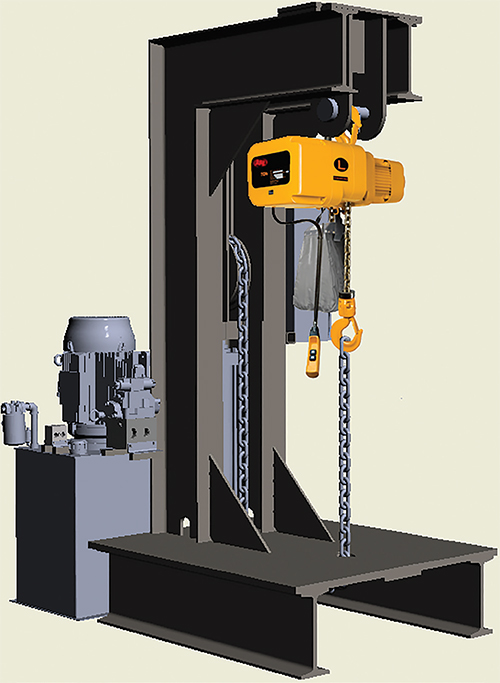
As JHF is also a hydraulics distributor, the engineers there knew that this problem could be addressed by using an electro-hydraulic motion controller to perform closed-loop control of the downward force on the hoists under test. The force was applied by a hydraulic cylinder pushing against a chain that goes through a set of pulleys in to align the force point right under the hoist (Figure 1).

The hydraulic system operates totally independently of the hoist, simply reacting to the movement of the hoist’s chain. The motion controller monitors the force that is pulling against the hydraulic cylinder, and as it sees the force begin to change, the controller acts to maintain the target force regardless of the chain’s direction of motion.
“If we didn’t use closed-loop control, there would be no way we could keep the force under precise control,” said Ken Strain, hydraulic engineer at JHF.
Choosing the motion controller
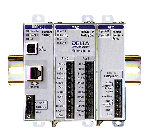
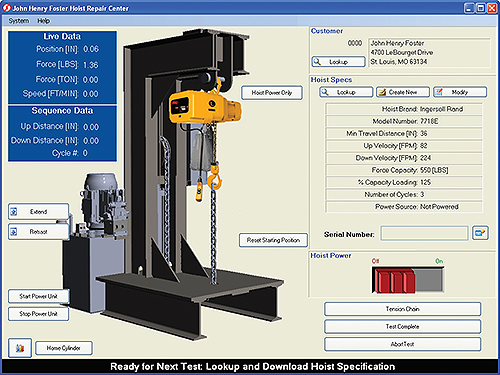
To control the hydraulic cylinder applying the force, JHF engineers chose Delta Computer’s RMC75 dual-axis electro-hydraulic controller (Figure 2). A PLC controls the hydraulic power unit, and a PC provides test parameters with an HMI (Figure 3) and log the testing results. All of these key system elements were connected through Ethernet/IP.


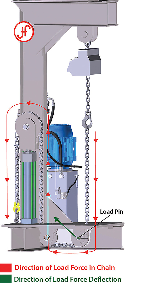
Force measurements come from a load pin that serves as the rotational axis for the lower chain pulley. The load pin is a unique strain gauge transducer that measures the deflection in the rotational pulley’s center hub caused by chain force (Figure 4). The load pin supplies a linear millivolt signal proportional to the encountered force, which is converted to a voltage signal using a 1-kHz amplifier.

JHF engineers initially tested having the motion controller measure the differential hydraulic pressure across the cylinder piston, but determined that running the chain around the other pulleys caused a negative impact on accuracy and precision. The pressure transducers were left in the cylinders to provide the option for future programming changes to implement feedback switching, a new capability supported by Delta motion controllers under the general heading of custom feedback, which allows selection of the most effective force sensors for a particular testing application. Although the pressure transducers proved to be less accurate on this application than the load pin, they are much less susceptible to damage since they are mounted away from any moving components.
In the event of a load pin failure, the force calculation can be switched on-the-fly to differential pressure using these transducers, which will allow testing to continue until the load pin can be repaired or replaced. The position information relating to the extension of the load chain was obtained by the motion controller through a direct connection to a magnetostrictive linear displacement transducer (LMDT) attached to the hydraulic cylinder. The cylinder itself is operated by a proportional servo valve controlled by the RMC75.
Automating the test sequence
One of the most useful features of the RMC75 is the ability to switch smoothly from controlling the position of the chain tensioning cylinder to controlling the force that it applies. In the JHF hoist tester, a testing protocol starts with the hydraulic cylinder fully retracted, achieved by a position command given to the motion controller by the PC. Then the operator is instructed to connect the chain to the hoist being tested. Following this, another position command is issued to extend the chain, along with the instruction for the controller to monitor the force that the cylinder is applying. When the chain is fully extended (such that the hoist is beginning to encounter a load), the motion controller sees the force begin to build, and then it switches to performing force control.
Once the controller is in force control, it informs the operator to proceed with the test. A Visual Basic program running on the PC goes through the test sequence. The RMC75 then simply responds to any motion of the chain by extending or retracting the cylinder to maintain the target force. Position information continues to be monitored during the hoist operation and is used to verify that the velocity of the hoist operation meets specified values. When the test is done, the motion controller ramps the force down and then switches back into position control, retracting the cylinder to provide slack to the chain to allow the operator to disconnect the hoist.
Tuning the motion was an issue for the JHF team because of the wide range of operation that must be supported.
“We needed to use multiple tuning points,” said Strain. “To simplify the task, we used the auto tuning feature of Delta’s RMCTools software for position tuning. It worked perfectly to get us really close to the optimal motion profile, and then we made tweaks to the force feedforward term in the closed-loop control algorithm to speed up the response.”
The test platform meets JHF’s needs for a facility that can test all the hoists that the company maintains.
“Without the new test platform we would need a warehouse full of weights to test all of the hoists,” said Parr. “And if we did, to meet ISO standards, we would need to calibrate all the weights. Now we just have one sensor that needs to be calibrated every year. There’s a lot less potential for errors and less opportunity for people to be hurt since heavy weights aren’t being carried around, and automated testing ensures the repeatability of test results.”
The new system also operates much more smoothly than manually-operated hoist testing procedures.
“Operators of manual test systems typically switch full force,” said Strain. “There would be no way to respond smoothly without the [controller], and we expect that we’ll have less maintenance problems over time due to that smooth operation.”
Delta Computer Systems
deltamotion.com


I’ve actually been taking some manufacturing classes right now. We are discussing hydraulics right now, so I really enjoyed this post. It’s neat to see something that can apply precise amounts of downward force to exercise electric pneumatic. Thanks for sharing this.