By Josh Cosford, Contributing Editor
It seems like a question with an easy answer, but you’d be surprised how often people ask, “how do relief valves work?” We in the fluid power industry take our knowledge for granted, but each and every one of us was at some point ignorant of literally every hydraulic component — the quest for knowledge has a beginning, but no end.

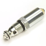
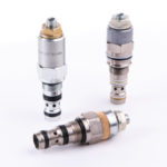
Relief valves are components used in hydraulic systems to limit fluid pressure in the part of the circuit they are installed. They are constructed with a ball, poppet or spool opposed by a spring and installed into a cavity or ported body. A poppet is a disc or cone shaped object that sits within an oppositely machined seat, and when forced closed by spring pressure, provides very low leakage. A spool is a cylindrical, machined steel rod with metering grooves or notches that is also opposed by spring pressure. A spool valve leaks more than a poppet valve, but the spool provides superior metering characteristics.
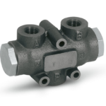
Relief valves are most often installed in a hydraulic system after the pump. This location provides the most direct and immediate response when the relief valve opens to bleed fluid to the reservoir, thereby reducing pressure equal to its spring setting. The relief valve will open as pressure caused by a downstream load or backpressure increases high enough to force the poppet or spool open against its spring.
A relief valve works by providing an excessively pressurized fluid an open path to tank with the goal of reducing work port pressure. As fluid pressure begins to rise, force from that pressure is applied to the bottom of the spool or poppet, similar to what occurs to the piston of a cylinder. The relief valve opens modestly at first, bleeding as little fluid is as required to maintain pressure as is required downstream. If downstream pressure continues to rise, so too does the force upon the poppet or spool, pushing it further against the spring until the point spring force is equaled by hydraulic force.
Relief valves experience pressure rise resulting from the combination of load pressure, backpressure and the energy required to flow through the valve itself. Cracking pressure is where initial fluid force overcomes the seated force of the spring. As the valve flows more fluid to the tank, the rate of pressure rise is stable since forces of the pressurized fluid counteract the compression rate of the spring. As the valve nears fully open, pressure rise increases again as the valve bottoms out and is subjected to flow forces.
As work or backpressure decreases and the valve starts to close, it does so at differing rates than what it opened at. The difference between the opening and closing curve is called its hysteresis and is indicative of the quality of its construction. Higher quality valves with advanced construction tend to have lower pressure rise with better hysteresis.