
By Josh Coford, Contributing Editor
Temperature, pressure, and displacement are typical transducer offerings. A linear displacement transducer measures linear position or distance, especially when high accuracy is needed.
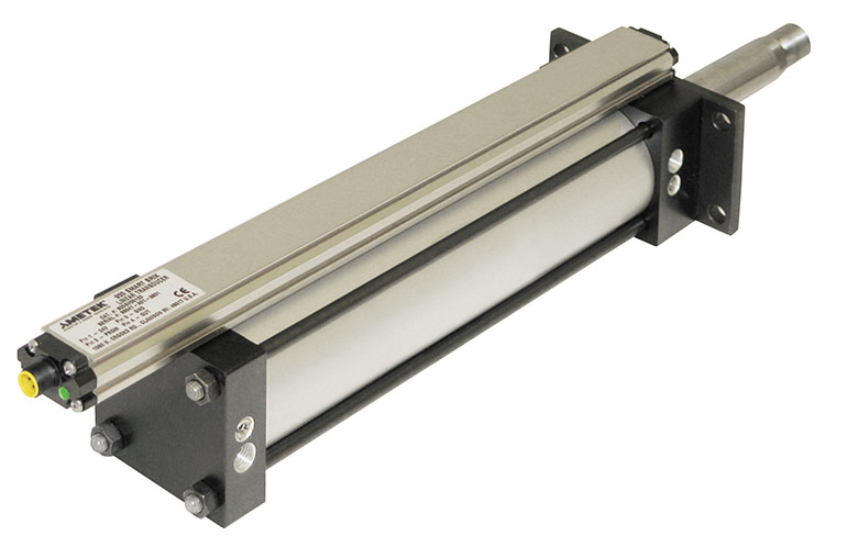
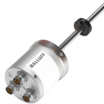
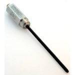
Linear transducers work using a principle called magnetostriction. A typical transducer uses three major components; the sensor assembly, a waveguide and a permanent magnet. The sensor assembly houses the control electronics and is responsible for sending and receiving the signal, then transmitting that signal to the PLC. The waveguide is the probe extending the length of the transducer, which emits and senses the magnetic field. Finally, the permanent magnet attaches to the traveling component the transducer measures.
The sensor assembly emits a current pulse that travels the length of the waveguide, emitting a magnetic field around the length of the probe. As the pulse passes through the field of the permanent magnet, the interaction creates a strain pulse that travels back down the length of the waveguide until the sensor assembly senses it.
The difference between the sent and received signal allows the sensing unit to precisely identify the distance of the permanent magnet along the length of the waveguide. Many designs are accurate to within hundredths of an inch or better.
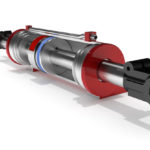
Also called a Linear Displacement Transducer, or LDT for short, common applications are inside linear actuators such as hydraulic cylinders. The output configurations include, but are not limited to, 0-10 V, 4-20 mA and CANBUS of various standards. When installed inside a hydraulic cylinder, the rod must be gun-drilled to allow space for the probe, and the magnet gets bolted to the piston’s back.
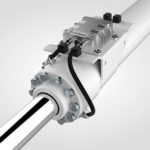
A port boss must be welded or machined into the “position 5” of the cylinder cap (its back end), where the transducer may be screwed tight upon installation. Some hydraulic cylinder mounts prevent the back end installation, such as with ME6 or MX1 mounts, and any clevis or rear pivot type cylinders. Rear mount cylinders will take advantage of internally mounted sensor assemblies which employ a connector assembly mounted to one of the available cap side surfaces.
Linear transducers may also operate outside of a linear actuator altogether. Stand-alone LDTs may be mounted beside or atop any actuator, where the rod end of the cylinder attaches to the mounting hardware at the end of the sensor. A bar or rod attaches the two, and the transducer is along for the ride to accurately measure linear displacement.