By Josh Cosford, Contributing Editor
The three most common ways to control hydraulic actuators are with lever valves, cartridge valves or sandwich valves. Lever valves are available as monoblock or stacked valves, and are primarily for directional control. Cartridge valves have nearly infinite possible combinations, but must be used with bodies or custom manifolds. Sandwich valves — also known as ISO, CETOP, sub-plate mounted or stack valves — are a way of creating hydraulic circuits by stacking valves atop each other and fixing them with bolts.

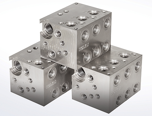
The bar manifolds used with sandwich valves are usually an afterthought compared to the circuit upon which they provide a home. However, you must smartly choose and apply the correct manifold for your application, or the entire circuit will perform poorly or not at all. As well, useful options are available to ease mounting and installation, so awareness of these options keeps you on your shop technicians’ Christmas shopping list.
Knowing the difference between a parallel and series circuit is the first, and most important, step. A parallel manifold is used on pressure compensated (variable displacement) pumps with closed P-port valves. All pressure ports are joined in parallel, and while the valves remain unshifted, the pump is on stand-by. With series circuits, flow from fixed pumps travels into the pressure port of the first valve and straight back into the tank port of the manifold. That tank port is also the pressure port for the second valve, whose tank line feeds the third valve’s pressure port. The series continues until the last valve, where its tank port exits the manifold to the reservoir.
A parallel manifold is almost never used with a fixed flow pump. Because the pump must flow somewhere, if it’s not being wasted as pure heat over the relief valve, it’ll blast out the weakest seal along its path. On the other hand, a variable displacement pump can be used with a series manifold, however, it doesn’t make sense. A variable displacement pressure compensated pump doesn’t like being unloaded at low pressure, so it will experience a severely reduced service life and cause a raucous in the meantime.
Bar manifolds are available with integrated relief valve cavities which provide a convenient location with no added plumbing. For the series manifold, it makes absolute sense to always include the relief cavity and then add a relief valve cartridge best suited to your application. A cartridge relief valve is literally one of the least expensive hydraulic components in existence, and it saves you the hassle of extra plumbing.
Parallel manifolds may or may not include a relief cavity. Pressure compensated pumps do their own pressure protection, although some like the added security of a relief valve. If you don’t choose the relief valve cavity for your manifold, you can still protect the entire manifold by installing a single P to T relief sandwich valve. Because the circuit is in parallel, it cares not about the directional valve under which the relief valve lives.
The major decisions of circuit type and relief option aside, other features are required to properly install and plumb the circuit. It goes without saying your manifold should suit your plumbing requirements, especially those geographically related. Your manifold can be had with SAE ports, BSPP ports, metric ports or even NPT ports, which will often be dictated by what’s common in your region. You can choose to add a gauge port to your manifold, as well, which allows for permanent fixing of a pressure gauge or test point. Most manifolds (especially with parallel circuits) have P & T ports on either end of the manifold for flexibility of installation.
If your valves are tightly packed or with lateral protrusions, the extra-wide spacing option will put a gap between each section of valves. This not only gives the extra space atop the manifold for stacked valves increased clearance, but also provides added space between the work ports. You’ll enjoy extra freedom of plumbing, especially if angle fittings are use directly off the manifold.
If your hydraulic system pumps at the higher end of the flow rating for your chosen valves, select the high-flow option for your manifold. The P, T and work ports are larger diameter to allow installation of larger fittings, and the cross-drillings internal to the block are larger for decreased pressure drop. Your pump and system also dictate the material of the manifold, which can be manufactured in aluminum for pressures up to 3,000 psi, or in steel or ductile iron for systems running up to 5,000 psi.
Finally, be sure you consider how the manifold is to be mounted. There will be tapped holes on the bottom or sides, allowing brackets and bolts to be attached. Often, the manifold is mounted with some clearance below, raising the manifold up and providing extra space for plumbing, which could be difficult should the manifold be mounted directly to a flat surface. At the very least, the manifold will have vertical through holes to accept long bolts to attach it to tapped holes on the mounting surface.
More than just a block with holes in it, the bar manifold is the foundation for countless hydraulic valve circuits. Many machine manufacturers only use stacked valves because of their ease of installation, flexibility in applications and ability to change and upgrade on the fly. If you decide to start using these useful blocks of metal, ensure you option it exactly as required by your application.


